Forming method of CMOS image sensor

An image sensor and pixel area technology, applied in the semiconductor field, can solve the problem of low collection efficiency of near-infrared light, achieve the effect of increasing mobility and increasing the number of photons

Active Publication Date: 2019-07-23
SHANGHAI HUALI MICROELECTRONICS CORP
View PDF9 Cites 2 Cited by
  • Summary
  • Abstract
  • Description
  • Claims
  • Application Information

AI Technical Summary

Problems solved by technology

[0006] The purpose of the present invention is to provide a method for forming a CMOS image sensor to solve the problem of low collection efficiency of near-infrared light in existing CMOS image sensors

Method used


Image

  • Forming method of CMOS image sensor
  • Forming method of CMOS image sensor
  • Forming method of CMOS image sensor

Examples


Embodiment Construction

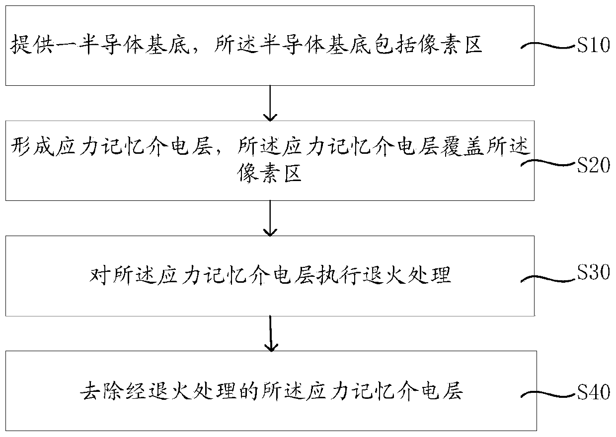
[0030] A method for forming a CMOS image sensor proposed by the present invention will be further described in detail below with reference to the drawings and specific embodiments. Advantages and features of the present invention will be apparent from the following description and claims. It should be noted that all the drawings are in a very simplified form and use imprecise scales, and are only used to facilitate and clearly assist the purpose of illustrating the embodiments of the present invention. In addition, the structures shown in the drawings are often a part of the actual structures. In particular, each drawing needs to display different emphases, and sometimes uses different scales.

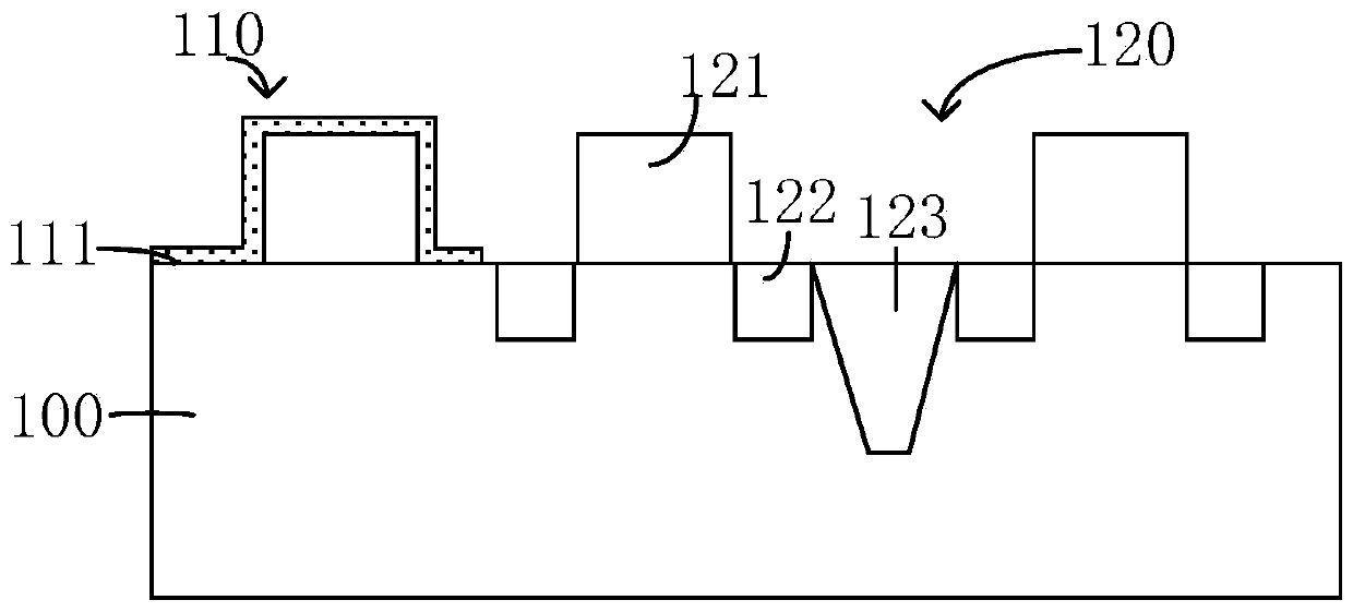
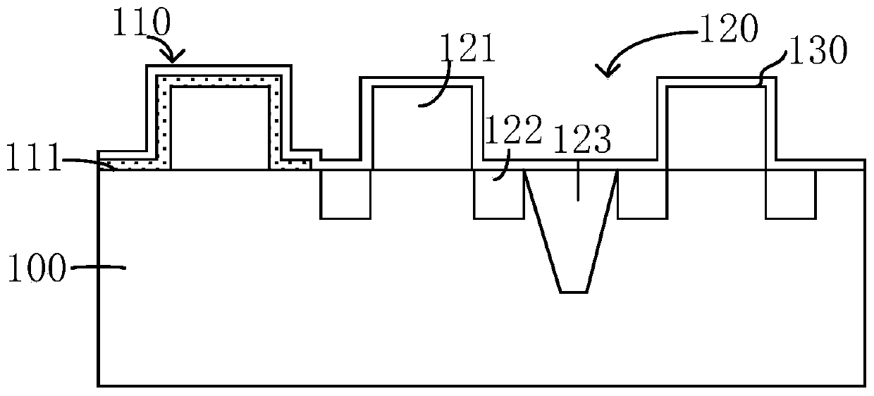
[0031] Please refer to Figure 1-Figure 5 , figure 1 is a flowchart of a method for forming a CMOS image sensor according to an embodiment of the present invention; Figure 2-Figure 5 It is a schematic structural diagram of each step of the method for forming a CMOS image sensor ac...


PUM

PropertyMeasurementUnit
Thicknessaaaaaaaaaa

Abstract

The invention provides a forming method of a CMOS image sensor, and the method comprises the steps: forming a self-aligned silicide region barrier layer, and covering a pixel region; forming a stressmemory dielectric layer, a grid electrode covering the pixel region and the pixel region, and a side wall; carrying out annealing treatment on the stress memory dielectric layer on the pixel region; and removing the stress memory dielectric layer on the pixel region. The invention also provides a CMOS image sensor, comprising a semiconductor substrate, wherein the semiconductor substrate comprisesa pixel region and a logic region; the pixel region and the logic region are each provided with a grid electrode and a side wall; a self-aligned silicide region barrier layer is formed on the pixel region, and the grid electrode and the side wall on the pixel region; a stress memory dielectric layer is arranged on the pixel region, high stress of the stress memory dielectric layer is transferredinto the pixel region through annealing, and the migration rate of electrons generated by near-infrared light can be increased in a stress mode, so that the electrons generated by near-infrared lightare increased to become signal charges, and the collection efficiency of the near-infrared light is improved.

Description

technical field [0001] The invention relates to the technical field of semiconductors, in particular to a method for forming a CMOS image sensor. Background technique [0002] With the development of the automobile industry, the Internet of Things and monitoring equipment, the consumption of image sensors has gradually increased, and the demand for near-infrared for vehicle recorders and monitoring equipment has also increased recently. Near-infrared technology is mainly used for image capture under dark light conditions, so that images can obtain more details. [0003] For the acquisition of near-infrared light (wavelength greater than 760nm), there are currently two commonly used structures and methods for FSI (Frontside Illumination, front-illuminated) mainly divided into two types: one is to use ultra-high energy implantation on N-type substrates to achieve ultra- Deep boron (B) implants (energy greater than 4MeV), and phosphorus (P) implants (energy greater than 7MeV)....

Claims


Application Information

Patent Timeline
IPC IPC(8): H01L27/146
CPCH01L27/14643H01L27/14683H01L27/14698
Inventor 顾珍田志王奇伟陈昊瑜
Owner SHANGHAI HUALI MICROELECTRONICS CORP
Why Eureka
Try Eureka