High-gain optical receiving antenna for indoor visible light communication

An optical receiving antenna and visible light communication technology, which is applied in the field of visible light communication, can solve the problems of little research on visible light receiving technology and difficult effective use of light energy, and achieve the effects of easy installation and operation, reduced communication blind spots, and meeting communication needs

Pending Publication Date: 2019-07-23
FUDAN UNIV
View PDF0 Cites 3 Cited by
  • Summary
  • Abstract
  • Description
  • Claims
  • Application Information

AI Technical Summary

Problems solved by technology

However, at present, the main areas of research on visible light communication technology include communication channel model, modulation and demodulation technology, and planning and layout optimization of light sources, etc., and there are few studies on visible light receiving technology.
[0004] In order to improve the receiving power and signal-to-noise ratio of the receiving end of the visible light communication system and ensure higher gain and larger field of view, domestic and foreign industries have proposed various design ideas for optical antennas, but the field of view of optical antennas and optical gain, channel There are always many limitations in performance improvement, and it is difficult to effectively use light energy

Method used


Image

  • High-gain optical receiving antenna for indoor visible light communication
  • High-gain optical receiving antenna for indoor visible light communication
  • High-gain optical receiving antenna for indoor visible light communication

Examples


Embodiment

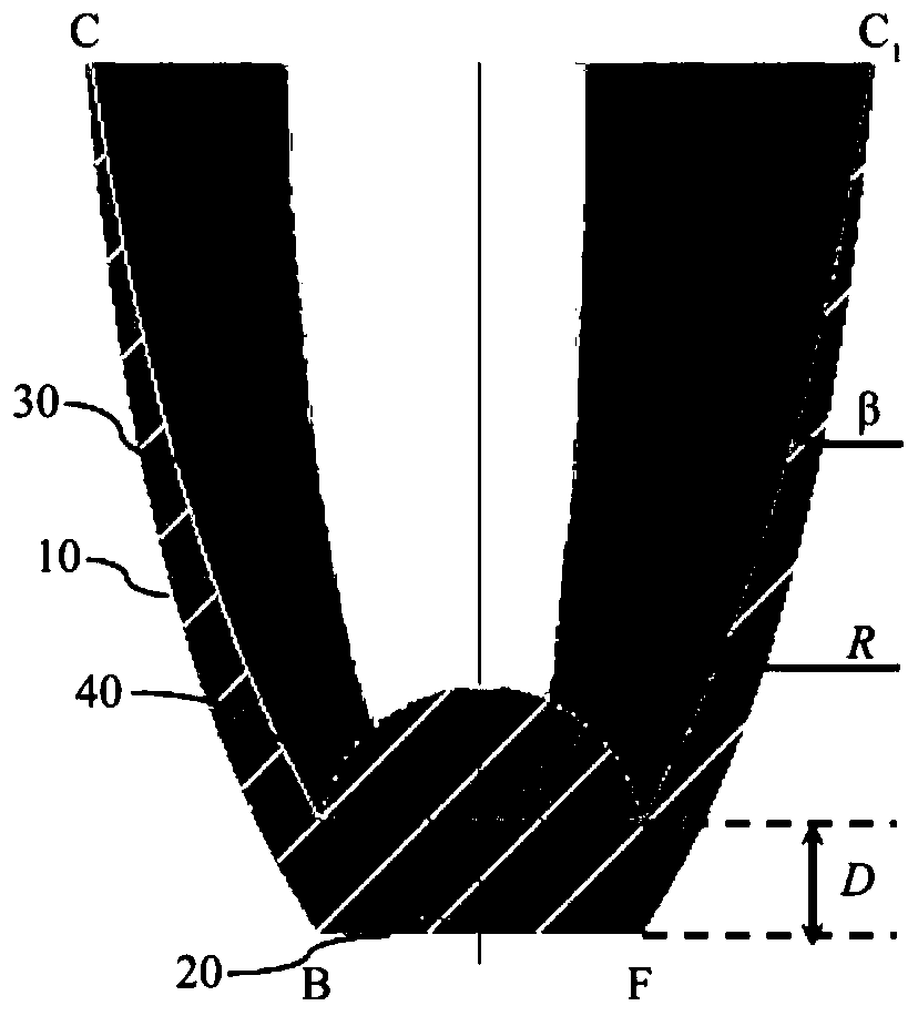
[0026] Such as figure 1 As shown, a high-gain optical receiving antenna for indoor visible light communication includes: a first outer surface 10, a second outer surface 20, a first inner surface 30 and a second inner surface 40; the first outer surface 10 It is a curved surface of revolution (convex surface) with the light-gathering characteristics of a paraboloid of revolution. The first inner surface 30 is also a curved surface of revolution with the light-gathering characteristics of a paraboloid of revolution. The first inner surface 30 is on the inner side of the first outer surface 10; the two curved surfaces of revolution intersect at the top (the intersecting line is a circle), record the intersection point of the two rotating curves forming two rotating surfaces as C 1 , these two rotation curves have the following relationship: the rotation curve of the first inner surface 30 is circled by the rotation curve of the first outer surface 10 around C 1 It is obtained b...


PUM


Abstract

The invention belongs to the technical field of visible light communication, and particularly relates to a high-gain optical receiving antenna for indoor visible light communication. The optical receiving antenna is of a rotary symmetrical structure and comprises a first outer surface, a second outer surface, a first inner surface and a second inner surface. The first outer surface and the first inner surface are rotary curved surfaces with rotary paraboloid condensation characteristics, and a rotary curve of the first inner surface is obtained after the rotary curve of the first outer surfacerotates around a vertex by an angle beta; the second outer surface is a plane, and the second inner surface is a spherical surface with the radius R; the optical field angle of the optical receivingantenna can reach 90 degrees and is increased by about 30 degrees compared with that of a compound parabolic concentrator; the optical gain reaches up to 21.53, the signal to noise ratio of an opticalreceiving end reaches 82.7944 dB or above, and the light spot area can be effectively reduced by 40% or above; the optical receiving antenna is of a non-composite multi-stage structure, is convenientto process and install, is green and environment-friendly, and can meet the communication requirements of an indoor visible light communication system.

Description

technical field [0001] The invention belongs to the technical field of visible light communication, and in particular relates to an optical receiving antenna. Background technique [0002] Light-emitting diodes (LEDs) have been widely used in visual transmission, information display, and lighting due to their advantages of high brightness, long life, and low power consumption. Therefore, LED visible light communication technology emerged as the times require. An emerging wireless communication technology that realizes information transmission by high-speed bright and flickering optical signals that are invisible to the human eye. It has the characteristics of green environmental protection, no electromagnetic interference, high data transmission rate, and low power consumption. [0003] In the VLC communication system, the optical antenna, as an important component of the receiving end, mainly plays the role of converging signal light, ensuring the transmission bandwidth of ...

Claims


Application Information

Patent Timeline
Patent Type & Authority Applications(China)
IPC IPC(8): H04B10/114H04B10/116G02B3/00
CPCG02B3/00H04B10/1149H04B10/116
Inventor 孔令豹彭星
Owner FUDAN UNIV
Why Eureka
Try Eureka