
An annular coaxial powder feeding device for ultra-high-speed laser cladding

A technology of coaxial powder feeding and laser cladding, which is applied in the coating process and coating of metal materials, can solve the problems of difficult production, low powder concentration, and low powder concentration, so as to improve the uniformity of space distribution and coating The effect of small layer surface roughness and small powder focus

Active Publication Date: 2020-06-12
XI AN JIAOTONG UNIV
View PDF8 Cites 0 Cited by
  • Summary
  • Abstract
  • Description
  • Claims
  • Application Information

AI Technical Summary

Problems solved by technology

Because the powder feeding needles need to be tilted at a certain angle and placed circularly around the central axis, the manufacturing process is difficult and the scrap rate is high, so the manufacturing cost is high, and affected by the processing accuracy, the powder output effect of each powder feeding needle cannot be guaranteed. exactly the same
In addition, due to the fact that most of the powder feeding needles are hollow straight tubes, it is difficult to manufacture, and due to the limitation of processing conditions, the size of the pinhole is limited, resulting in poor powder convergence of the needle-type coaxial powder feeding device, large focus of convergence, low powder concentration, and flow out of the needle. After losing the constraint, there is a certain divergence angle; and the inclination angle of the powder feeding needle and the distance between the needles cannot obtain the optimal parameters, so that the concentration of the powder is low, the flight time of the powder in the laser is shortened, and the powder cannot be melted, resulting in waste

Method used


Image

  • An annular coaxial powder feeding device for ultra-high-speed laser cladding
  • An annular coaxial powder feeding device for ultra-high-speed laser cladding
  • An annular coaxial powder feeding device for ultra-high-speed laser cladding

Examples


Embodiment Construction

[0043] In order to make the above objectives, features and advantages of the present invention more obvious and understandable, the present invention will be further described in detail below in conjunction with the accompanying drawings and specific embodiments.

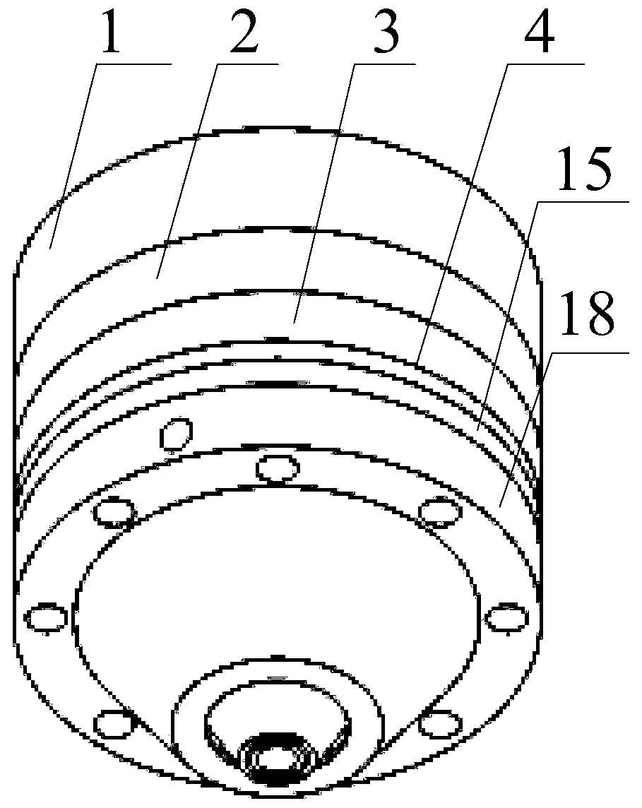
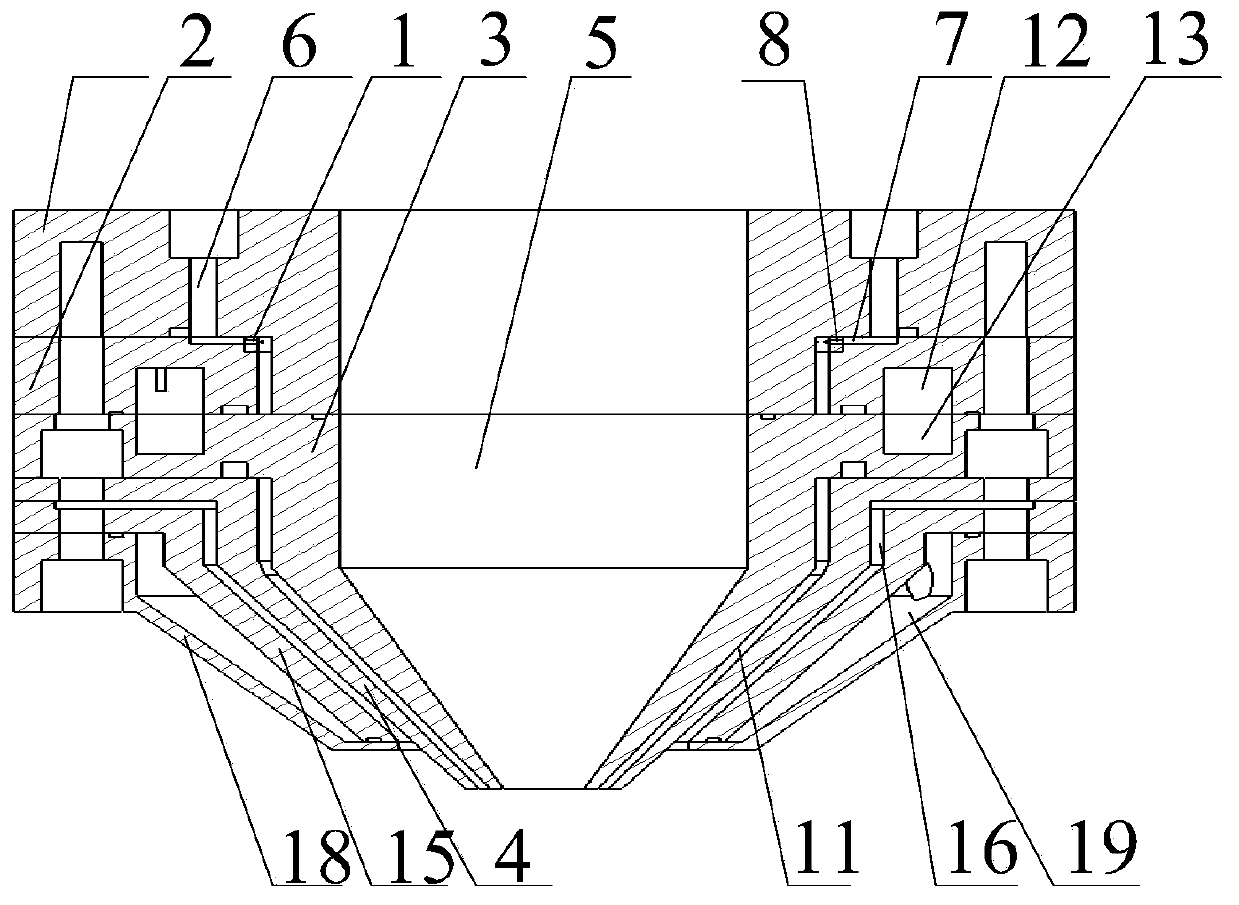
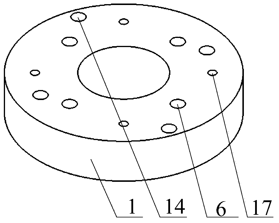
[0044] Reference figure 1 , Shows a schematic diagram of the three-dimensional structure of an annular coaxial powder feeding device for ultra-high-speed laser cladding according to an embodiment of the present invention; figure 2 , Shows a schematic cross-sectional structure diagram of an annular coaxial powder feeding device for ultra-high-speed laser cladding according to an embodiment of the present invention. The annular coaxial powder feeding device of the embodiment of the present invention includes:

[0045] The laser optical system, and the top part 1, the middle part 2, the first cone part 3 and the second cone part 4 connected sequentially from top to bottom, the top part 1, the middle part 2, the first The co...


PUM


Abstract

The invention is applied to the field of laser processing, and provides an annular coaxial powder feeding device for ultra-high-speed laser cladding. The annular coaxial powder feeding device comprises a laser optical system, a top part, a middle part, a first conical part and a second conical part, wherein the top part, the middle part, the first conical part and the second conical part are sequentially connected from top to bottom, and the axes of the top part, the middle part, the first conical part and the second conical part are in communication to form a laser chamber. According to the annular coaxial powder feeding device, two front wall surfaces are used for finishing the reduction of the powder, the powder is uniformly dispersed by adopting two-stage powder distributing program ofa transverse powder feeding through hole and a longitudinal powder feeding through hole, powder power is provided by accelerating the carrier gas through a conical shrinking chamber, so that the effects of small powder focus and high convergence concentration are achieved, moreover, the spatial distribution uniformity at the position of the powder focal point can be improved by using the powder distribution program, and the surface roughness of the prepared coating is smaller.

Description

Technical field [0001] The invention relates to the field of laser processing, in particular to an annular coaxial powder feeding device for ultra-high-speed laser cladding. Background technique [0002] The key parts of high-end equipment in the fields of vehicles, ships, iron and steel metallurgy, energy and chemical industries often require special treatment for their surface performance requirements such as wear resistance and corrosion resistance. The common types of processes mainly include electroplating, thermal spraying, surfacing and laser cladding. The electroplating technique produces a thin coating, generally no more than 100μm. Under special conditions, it is easy to cause the entire part to fail due to coating failure. In addition, the coating is poorly bonded to the substrate, generally not exceeding 100Mpa, and has poor corrosion resistance and is easy to peel off. In addition, serious waste of resources and environmental pollution in the production process is a...

Claims


Application Information

Patent Timeline
Patent Type & Authority Patents(China)
IPC IPC(8): C23C24/10
CPCC23C24/10
Inventor 李成新李岩刘伊李长久
Owner XI AN JIAOTONG UNIV
Learn More