Vector controlled "dead-time effect" compensation method for permanent magnet synchronous motor

A permanent magnet synchronous motor, dead-time compensation technology, applied in motor control, vector control system, motor generator control and other directions, can solve the problem of compensation effect dependence, adding additional hardware, complex calculation, etc., to save hardware cost, calculation Accurate and fast dead zone compensation effect

Inactive Publication Date: 2019-07-30
BEIJING MECHANICAL EQUIP INST
View PDF11 Cites 17 Cited by
  • Summary
  • Abstract
  • Description
  • Claims
  • Application Information

AI Technical Summary

Problems solved by technology

[0006] In view of the above analysis, the present invention aims to provide a permanent magnet synchronous motor vector control "dead zone effect" compensation method to solve the problem tha

Method used


Image

  • Vector controlled "dead-time effect" compensation method for permanent magnet synchronous motor
  • Vector controlled "dead-time effect" compensation method for permanent magnet synchronous motor
  • Vector controlled "dead-time effect" compensation method for permanent magnet synchronous motor

Examples


Embodiment 1

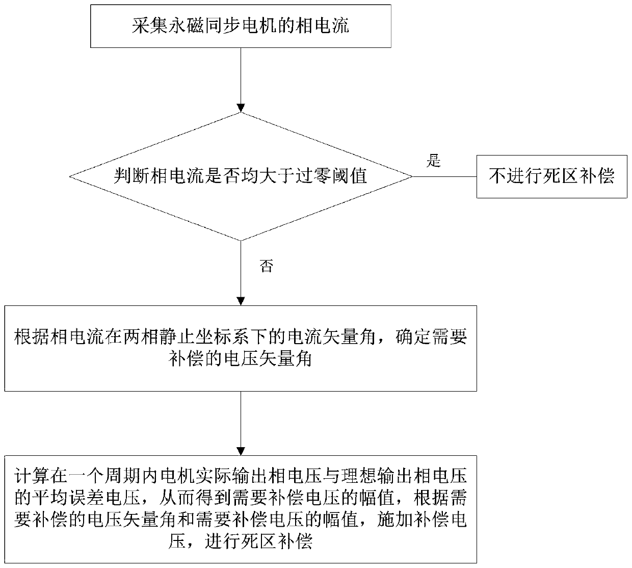
[0050] A specific embodiment of the present invention discloses a compensation method for "dead zone effect" of permanent magnet synchronous motor vector control, figure 1 A schematic flow chart of the method;

[0051] Described method specifically comprises the following steps:

[0052] Step S1, collect the phase current i of the permanent magnet synchronous motor a , i b , i c ;

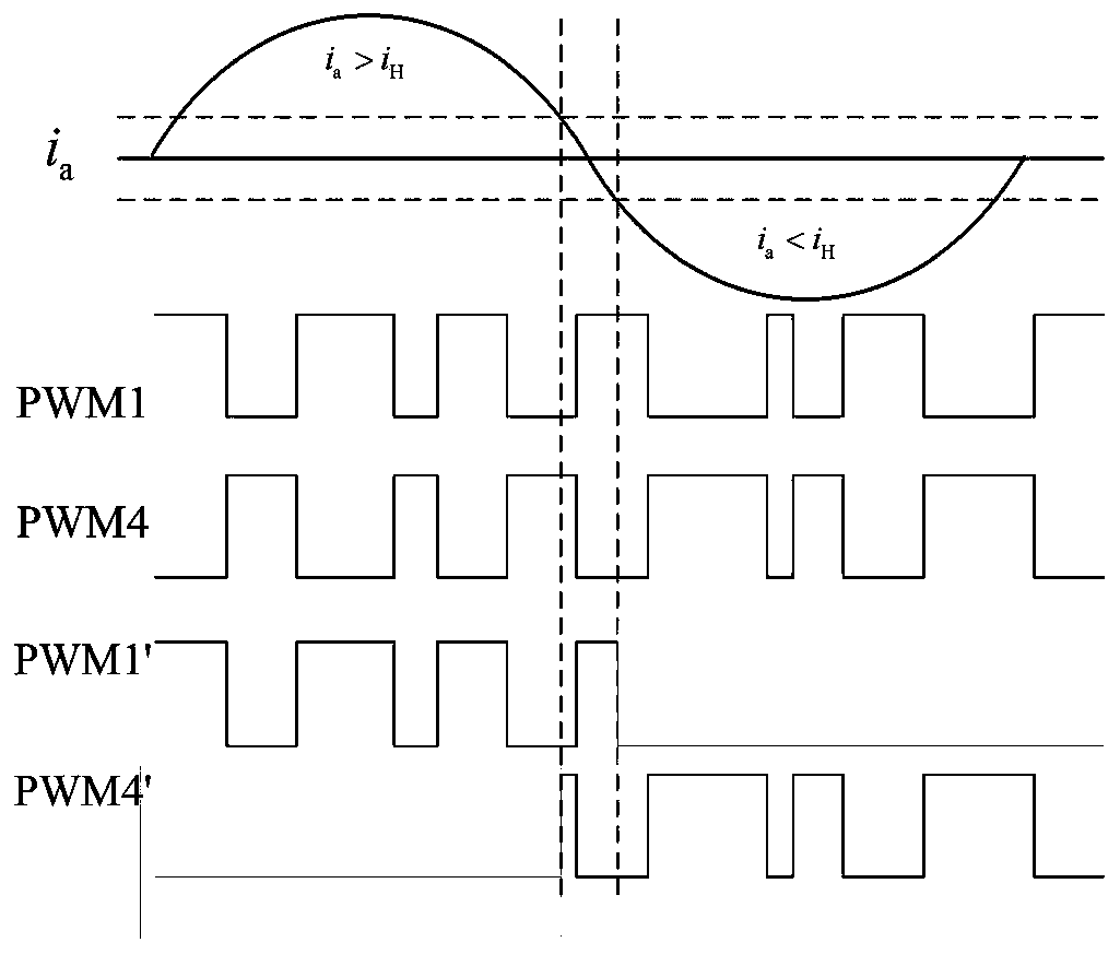
[0053] Step S2, respectively judge |i a |, |i b |, |i c |with zero-crossing threshold i H size, if|i a |, |i b |or|i c |Less than zero-crossing threshold i H , then carry out dead zone compensation, jump to step S3, otherwise do not perform dead zone compensation;

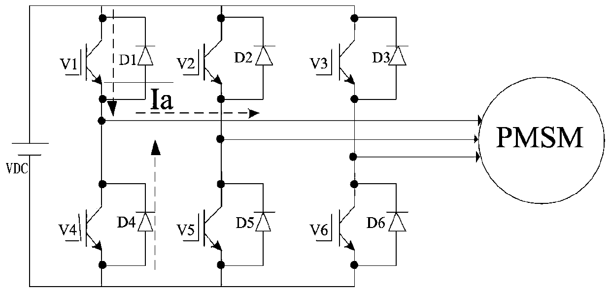
[0054] figure 2 It is the main circuit structure diagram of the three-phase voltage source PWM inverter motor load, the PWM inverter is connected to the PWM load, and the influence of the dead time on the output voltage is analyzed by taking the a-phase bridge arm as an example, and the current polarity is defined by Posi...

Embodiment 2

[0086] Another specific embodiment of the present invention discloses a permanent magnet synchronous motor vector control "dead zone effect" compensation system, the structural diagram of the system is as follows Image 6 As shown; the system includes a phase current acquisition module, a dead zone compensation execution discrimination module, a compensation voltage vector angle determination module and a dead zone compensation module,

[0087] The phase current acquisition module is used to acquire the phase current i of the permanent magnet synchronous motor a , i b , i c ;

[0088] The dead zone compensation execution judgment module is used to determine whether to perform dead zone compensation, if |i a |, |i b |or|i c |Less than zero-crossing threshold i H , the dead zone compensation is performed, otherwise no dead zone compensation is performed;

[0089] When performing dead zone compensation, the current vector angle calculation module is used to calculate the c...


PUM


Abstract

The invention relates to a vector controlled "dead-time effect" compensation method for a permanent magnet synchronous motor, and belongs to the technical field of permanent magnet synchronous motors,and solves the problems in the prior art such as compensation effect dependent on the accuracy of the motor model, need for additional hardware, complicated calculation and compensation by mistakes.The vector controlled "dead-time effect" compensation method for permanent magnet synchronous motor comprises the following steps: collecting phase currents ia, ib, ic of the permanent magnet synchronous motor; respectively comparing |ia|, |ib| or |ic| with a zero-cross threshold iH, if |ia|, |ib| or |ic| is less than or equal to the zero-cross threshold iH, performing the dead time compensation;otherwise, not performing the dead time compensation. The dead time compensation comprises steps of determining a voltage vector angle that needs to be compensated; calculating an average error voltage of the output phase voltages in a cycle, thereby obtaining the amplitude of the voltage to be compensated, applying a compensation voltage according to the voltage vector angle to be compensated andthe amplitude of the voltage to be compensated for performing a dead time compensation, so as to the accurate and fast dead time compensation.

Description

technical field [0001] The invention relates to the technical field of permanent magnet synchronous motors, in particular to a compensation method for "dead zone effect" of vector control of permanent magnet synchronous motors. Background technique [0002] In the AC permanent magnet synchronous motor (PMSM) speed control system, the application of voltage pulse width modulation (PWM) technology realizes the real-time control of the dynamic torque of the AC servo motor and greatly improves the dynamic performance of the servo system. However, for the PWM inverter, in order to prevent the two power devices on the same bridge arm of the inverter from passing through and destroying the inverter, it is necessary to artificially add a dead time to the control signal, and both devices are cut off during the dead time. In addition, when the inverter is working, there is a delay in the switching time, and the turn-off time is usually delayed longer, all of which lead to a difference...

Claims


Application Information

Patent Timeline
IPC IPC(8): H02P21/00H02P21/04H02P27/08
CPCH02P21/00H02P21/04H02P27/08H02P2207/05
Inventor 王昊高润鹏李嗣研蔡霖崔广志李建冬
Owner BEIJING MECHANICAL EQUIP INST
Why Eureka
Try Eureka