Efficient transmission mechanism of water turbine

A technology of transmission mechanism and water turbine, which is applied in the direction of machines/engines, engine components, reaction engines, etc., can solve the problems of not being able to change output power according to needs, not being able to make good use of water resources, and unfavorable normal operation of equipment, so as to achieve convenience Output power, good for voltage regulation, and easy to control

Pending Publication Date: 2019-08-02
天津天发总厂机电设备有限公司
View PDF3 Cites 3 Cited by
  • Summary
  • Abstract
  • Description
  • Claims
  • Application Information

AI Technical Summary

Problems solved by technology

However, it is found through research that the present invention cannot change the output power according to the needs, and it is inconvenient to carry out maintenance, which is not conducive to ensuring the normal operation of the equipment
[0005] The invention of CN101984254A discloses a transmission mechanism of the water guide part of the water turbine, which simplifies the transmission process of the unit, does not cause the transmission mechanism to loosen due to the vibration of the unit, and when the guide vane is blocked by foreign objects and cannot be closed normally, the relay The force on the device is transmitted to the connecting plate through the control ring, and the connecting plate is stressed. When the force is greater than the bearing limit of the connecting plate, the connecting plate is bent. At this time, the signal collector sends an alarm signal, the unit shuts down, and the connecting plate is replaced. , and the production of the connecting plate is simpler than that of the pull-off pin, and the cost of manufacturing is lower than that of the pull-off pin, but it is found through research that the present invention cannot make good use of water resources, resulting in waste of water resources and reducing the conversion rate

Method used


Image

  • Efficient transmission mechanism of water turbine
  • Efficient transmission mechanism of water turbine
  • Efficient transmission mechanism of water turbine

Examples


Embodiment 1

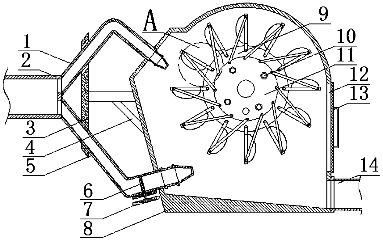
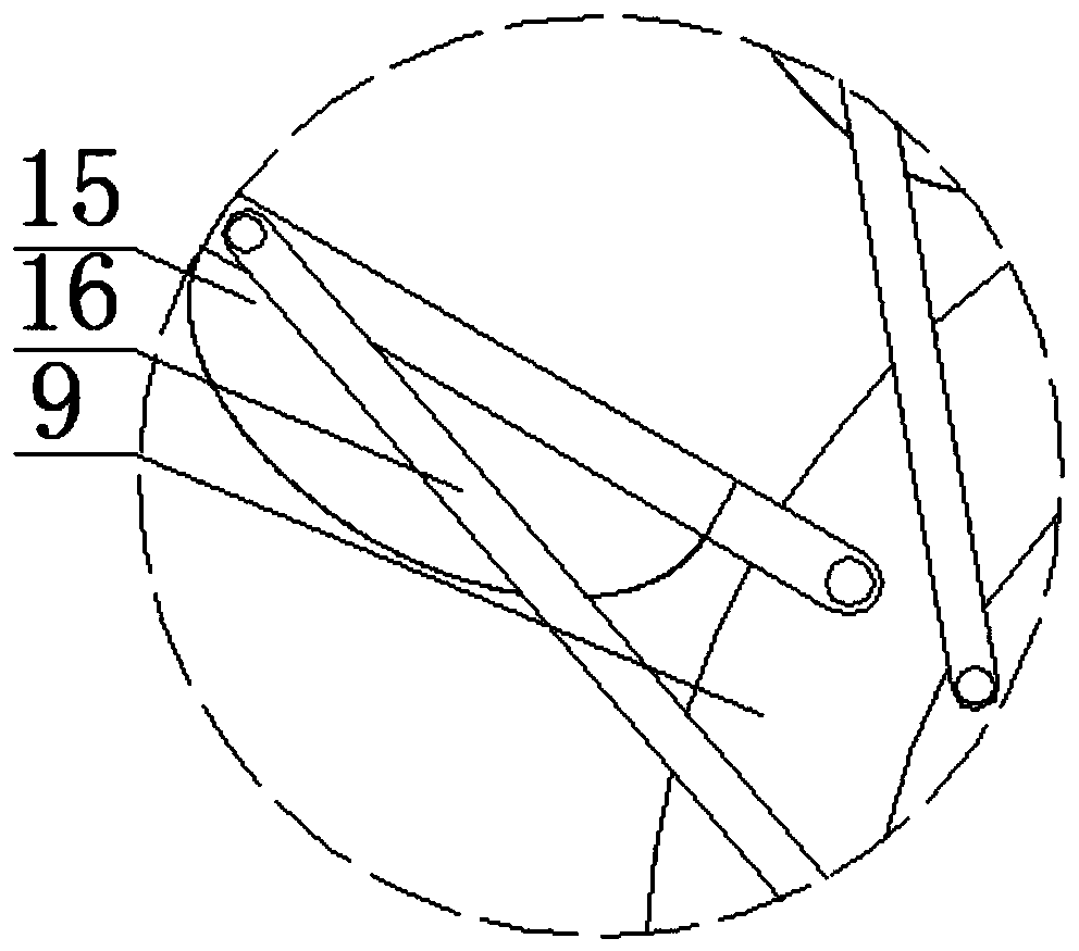
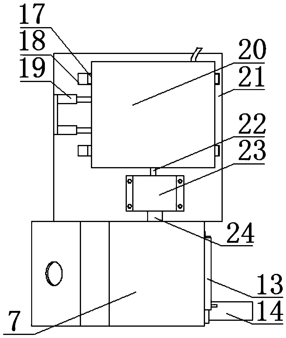
[0037] refer to figure 1 , 3 , 4, 5, 6, 8, a high-efficiency transmission mechanism of a water turbine, including a first housing 8, the bottom of the first housing 8 is inclined, so as to facilitate the flow of accumulated water, and then facilitate discharge, which is convenient for excessive accumulated water. To affect the rotation of the first turntable 9, a bottom plate 21 is fixed on one side of the lower end of the first housing 8, a second rotating shaft 24 is rotatably sleeved on one end side wall of the first housing 8, and a second rotating shaft 24 is fixed on one end of the second rotating shaft 24. A turntable 9, and the first turntable 9 is located in the first housing 8, the first turntable 9 is equidistantly provided with a plurality of rotating plates 15, one side of the first case 8 is provided with a water delivery device, and the water delivery device Corresponding to the rotating plate 15, so that the water impacts the rotating plate 15 conveniently, an...

Embodiment 2

[0051] refer to figure 1 , 2 , 3, 4, 5, 6, 7, 8, a high-efficiency transmission mechanism of a water turbine, including a first housing 8, the bottom of the first housing 8 is arranged obliquely, so as to facilitate the flow of accumulated water, and then facilitate discharge and accumulation Too much water will affect the rotation of the first turntable 9. A bottom plate 21 is fixed on one side of the lower end of the first casing 8, and a second rotating shaft 24 is sleeved on one end side wall of the first casing 8. The second rotating shaft 24 One end is fixed with a first turntable 9, and the first turntable 9 is located in the first casing 8, a plurality of rotating plates 15 are arranged at equal intervals on the first turntable 9, and a water delivery device is installed on one side of the first casing 8. , the water delivery device corresponds to the rotating plate 15, so that the water impacts the rotating plate 15 conveniently, and then can drive the first rotating...

Embodiment 3

[0067] refer to figure 1 , 3 , 4, 5, 6, 8, a high-efficiency transmission mechanism of a water turbine, including a first housing 8, the bottom of the first housing 8 is inclined, so as to facilitate the flow of accumulated water, and then facilitate discharge, which is convenient for excessive accumulated water. To affect the rotation of the first turntable 9, a bottom plate 21 is fixed on one side of the lower end of the first housing 8, a second rotating shaft 24 is rotatably sleeved on one end side wall of the first housing 8, and a second rotating shaft 24 is fixed on one end of the second rotating shaft 24. A turntable 9, and the first turntable 9 is located in the first housing 8, the first turntable 9 is equidistantly provided with a plurality of rotating plates 15, one side of the first case 8 is provided with a water delivery device, and the water delivery device Corresponding to the rotating plate 15, so that the water impacts the rotating plate 15 conveniently, an...


PUM


Abstract

The invention discloses an efficient transmission mechanism of a water turbine. The efficient transmission mechanism comprises a first shell, a bottom plate is fixedly arranged on one side of the lower end of the first shell, the side wall of one end of the first shell is rotationally sleeved with a second rotating shaft, a first turntable is fixedly arranged at one end of the second rotating shaft and located in the first shell, and a plurality of rotating plates are arranged on the first turntable at equal intervals; a water delivery device is arranged on one side of the first shell in a penetrating manner; and the other end of the second rotating shaft is rotationally sleeved with a second shell, a fourth gear is fixedly arranged at the other end of the second rotating shaft, and the fourth gear is located in the second shell. The efficient transmission mechanism can effectively utilize water resources, improves the conversion efficiency of water potential energy and is convenient to adjust, and therefore achieves the purpose of stable and efficient transmission, and the efficient transmission mechanism can ensure the normal work of water turbine power generation equipment, improves the output power and is conducive to stabilizing the voltage and prolonging the service life of the equipment.

Description

technical field [0001] The invention relates to the technical field of water turbines, in particular to a high-efficiency transmission mechanism of a water turbine. Background technique [0002] A water turbine is a power machine that converts the energy of water flow into rotational mechanical energy, and it belongs to the turbomachinery in fluid machinery. As early as around 100 BC, the prototype of the water turbine appeared in China - the water wheel, which was used to lift irrigation and drive grain processing equipment. Most modern water turbines are installed in hydropower stations to drive generators to generate electricity. In a hydropower station, the water in the upstream reservoir is led to the turbine through the diversion pipe, which drives the turbine runner to rotate and drives the generator to generate electricity. The water that has done work is discharged downstream through the tail water pipe. The higher the water head and the greater the flow, the gre...

Claims


Application Information

Patent Timeline
Patent Type & Authority Applications(China)
IPC IPC(8): F03B13/00F03B11/00F03B11/02F03B3/14F03B15/04
CPCF03B3/123F03B3/145F03B11/00F03B11/004F03B11/025F03B13/00F03B15/04Y02E10/20
Inventor 马金璐代志娟严森
Owner 天津天发总厂机电设备有限公司
Why Eureka
Try Eureka