Automatic tuning short-wave loop antenna and tuning method thereof

An automatic tuning and loop antenna technology, applied in loop antennas, variable reactance loop antennas, antennas, etc., can solve the problems of inconvenient deployment and folding, large volume, low efficiency of short-wave antennas, etc., and achieve low loss and meet portability , to achieve the effect of no blind zone communication

Active Publication Date: 2019-08-02
XIAN XINGWANG ANTENNA TECH
View PDF9 Cites 3 Cited by
  • Summary
  • Abstract
  • Description
  • Claims
  • Application Information

AI Technical Summary

Problems solved by technology

[0003] In order to solve the problems of low efficiency, large size, blind spots in communication, and inconvenient deployment and folding of the above-mentioned short-wave antenna, the present invention proposes an automatic tuning short-wave loop antenna and its tuning method

Method used


Image

  • Automatic tuning short-wave loop antenna and tuning method thereof
  • Automatic tuning short-wave loop antenna and tuning method thereof
  • Automatic tuning short-wave loop antenna and tuning method thereof

Examples


Embodiment 1

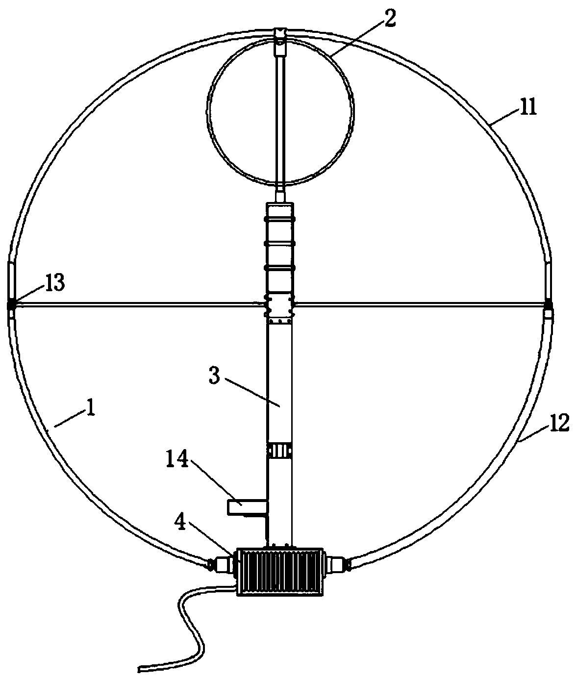
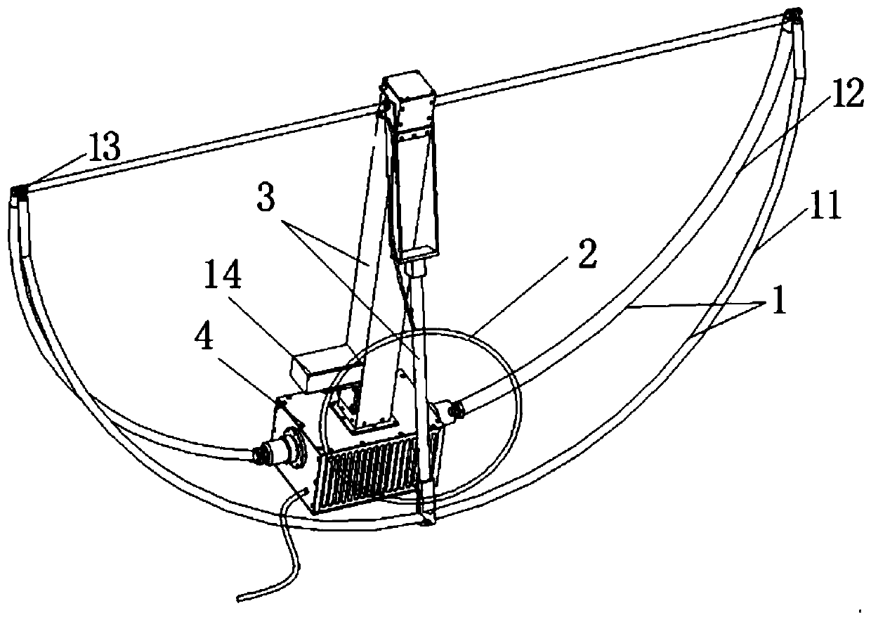
[0041] In this embodiment, the coupling ring 2 is located in the upper half of the radiation ring 1, the radiation ring 1 is made of a hollow metal ring, the hollow metal ring is divided into an upper half ring 11 and a lower half ring 12, and the upper half ring 11 and The lower half rings 12 are connected together by the connecting piece 13 , and the transmission mechanism 14 is driven by the motor to bend the connecting piece 13 by tightening the connecting piece 13 , so as to realize the expansion and contraction of the radiation ring 1 and the support rod 3 .

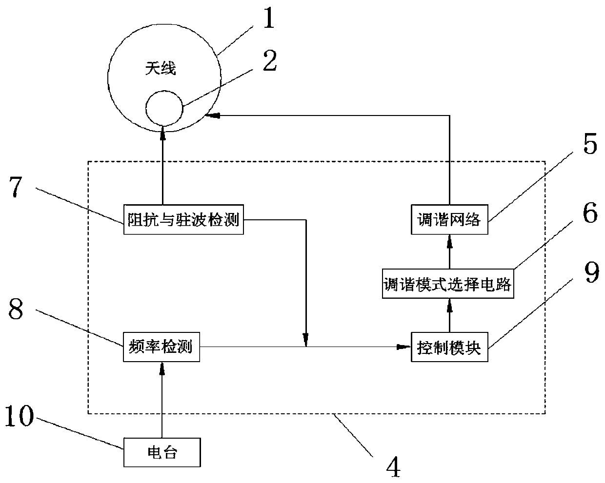
[0042] The frequency detection unit 8 detects that the working frequency of the radio station 10 is 18MHz, and the impedance and standing wave detection unit 7 detects that the input impedance of the antenna is 30-80j, and the control unit 9 judges that it is working at a high frequency. The control unit 9 switches to the matching network tuning mode by controlling the tuning mode selection circuit 6. At this time,...

Embodiment 2

[0044] In this embodiment, the coupling ring 2 is positioned at the lower half of the radiation ring 1. The radiation ring 1 is made of a hollow metal ring. The casing is insulated, and the other end is connected to the radio through the feeder socket. The hollow metal ring is divided into an upper half ring 11 and a lower half ring 12. The upper half ring 11 and the lower half ring 12 are connected together by a connecting piece 13, and the transmission mechanism 14 is driven by the motor to make the connecting piece 13 is bent to realize the expansion and contraction of the radiation ring 1 and the support rod 3 .

[0045] In this embodiment, except that the position of the coupling ring 2 inside the radiation ring 1 is different, the others are the same as the embodiment 1.

[0046] The impedance matching method for the high-end frequency band (12-30 MHz) is the same as that of Embodiment 1.

Embodiment 3

[0048] In this embodiment, the coupling ring 2 is located in the upper half of the radiation ring 1, the radiation ring 1 is made of a hollow metal ring, the hollow metal ring is divided into an upper half ring 11 and a lower half ring 12, and the upper half ring 11 and The lower half rings 12 are connected together by the connecting piece 13, and the transmission mechanism 14 is driven by the motor to bend the connecting piece 13 by tightening the wire in the connecting piece 13, so as to realize the expansion and contraction of the radiation ring 1 and the support rod 3.

[0049] The frequency detection unit 8 detects the operating frequency and impedance of the radio station 10 and the standing wave detection unit 7 detects the input impedance of the antenna and then transmits it to the control unit 9. After receiving the operating frequency and impedance value, the control unit 9 compares it with the preset value and judges For the low-end frequency band (3-12MHz), the inpu...


PUM


Abstract

The invention provides an automatic tuning short-wave loop antenna and a tuning method thereof and belongs to the technical field of communication antenna equipment. The antenna specifically includesa radiation ring, a coupling ring, a support rod and an antenna tuning unit box, wherein the coupling ring is arranged at an inner side of the radiation ring, the coupling ring is connected with the antenna tuning unit box through the support rod, the antenna tuning unit box includes a tuning network unit, a tuning mode selection circuit, an impedance and standing wave detection unit, a frequencydetection unit and a control unit, the frequency detection unit is connected with the impedance and standing wave detection unit and the control unit, the control unit is connected with the tuning mode selection circuit, the tuning mode selection circuit is connected with the tuning network unit, and the tuning mode selection circuit is electrically connected with the radiation ring and the coupling ring through a control switch. The antenna is advantaged in that antenna tuning utilizes a hybrid tuning mode, namely, a low band coupled tuning mode and a high band matching network tuning mode, and problems of low efficiency, large volume, dead communication zone and carrying inconvenience of a short-wave antenna in the prior art are solved.

Description

technical field [0001] The invention belongs to the technical field of communication antenna equipment, and in particular relates to an automatic tuning short-wave loop antenna and a tuning method thereof. Background technique [0002] The short-wave antennas currently used in the market have low antenna efficiency. Some short-wave antennas with wide frequency bands are relatively large in size and high in manufacturing costs. Occasion does not apply. The short-wave communication frequency band is wide, and the input impedance of the narrow-band antenna changes with the frequency, which is a complex impedance. The general loop antenna realizes the impedance matching between the transmitters of the antenna through the adjustable capacitor connected at the end of the large loop. The adjustable range is generally in 3-12MHz. Existing short-wave communication mainly includes whip antenna, half-loop antenna and dipole antenna. The piggyback type 2.4m or 10m whip antenna has an...

Claims


Application Information

Patent Timeline
Patent Type & Authority Applications(China)
IPC IPC(8): H01Q5/50H01Q1/12H01Q1/50H01Q7/00
CPCH01Q1/12H01Q1/50H01Q7/005H01Q5/50
Inventor 张辉秦旭毛子强岳正鹏陈杰
Owner XIAN XINGWANG ANTENNA TECH
Why Eureka
Try Eureka