
Fast and reliable current limiting device for faults of traction power supply system

A technology of traction power supply system and current limiting device, which is applied in the direction of circuit device, emergency protection circuit device, emergency protection circuit device for limiting overcurrent/overvoltage, etc., and can solve the problem of high cost control unit operation and maintenance, short circuit current response Overtime, low voltage resistance of electronic switches, etc., to achieve the effect of high voltage resistance, obvious current limiting effect, and fast switching time

Inactive Publication Date: 2019-08-02
成都智源电气有限责任公司
View PDF0 Cites 4 Cited by
  • Summary
  • Abstract
  • Description
  • Claims
  • Application Information

AI Technical Summary

Problems solved by technology

Low-temperature or normal-temperature superconducting current-limiting devices have not been popularized and applied on a large scale due to their high cost and immature technology development; power electronic current-limiting devices and mechanical current-limiting devices are currently the main hot spots of development, but power electronics The electronic electronic switch of the current device has low withstand voltage and low working efficiency. The mechanical fault current limiting device has high cost and operation and maintenance problems of the control unit, and the electromagnetic switch type fault current limiting device also has short-circuit current response. time too long

Method used


Image

  • Fast and reliable current limiting device for faults of traction power supply system

Examples


Embodiment Construction

[0026] The present invention will be further described below in conjunction with the accompanying drawings and actual operation examples, so that the features and advantages of the present invention can be more easily understood by those skilled in the art.

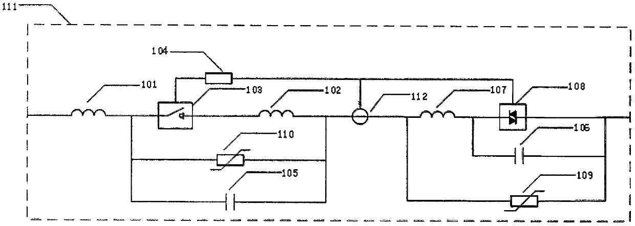
[0027] like figure 1 As shown, a traction power supply system failure fast and reliable current limiting device, including the current limiting reactor L 1 (101), current limiting reactor L 2 (102), electromagnetic ultra-high-speed mechanical switch (103), switch control unit (104), capacitor C 1 (105), capacitor C 2 (106), current limiting reactor L 3 (107), anti-parallel thyristor G (108), arrester K 1 (109), arrester K 2 (110), insulation cabinet (111), current transformer (112).

[0028] The traction power supply system failure fast and reliable current limiting device has two three parallel branches connected in series, one of the front parallel branches is provided with a capacitor C 1 , a lightning arrester ...


PUM


Abstract

The invention provides a fast and reliable current limiting device for faults of a traction power supply system. The device is composed of a main switch and a standby switch, and includes a main control unit, an electromagnetic ultra-high speed switch, current limiting reactors, an insulation cabinet, a current transformer, a switch control unit, a lightning protection unit, an inlet and outlet wire terminal, a standby solid-state switch and the like, wherein the main control unit controls the operation of an anti-parallel thyristor of the electromagnetic ultra-high speed mechanical switch andthe standby switch; when the circuit is normal in operation, both the electromagnetic ultra-high speed mechanical switch and the solid-state switch are in an off state, a current limiting inductor and a capacitor constitute series resonance, and the current limiting device shows zero impedance to the outside; and when the circuit has an overcurrent or short circuit fault, the switch control unitautomatically detects that the current flowing through the circuit exceeds the set threshold, the electromagnetic ultra-high speed mechanical switch is quickly closed when the short-circuit current passes the zero point at the first big half wave, the inductor and the capacitor constitute parallel resonance at the main switch, and the current limiting device shows high impedance so as to suppressthe short-circuit current.

Description

technical field [0001] The invention relates to the field of traction power supply systems, in particular to a fast and reliable current limiting device for traction power supply system faults. The current limiting device is suitable for reliable and rapid current limiting processing when overcurrent or short circuit faults occur in traction power supply systems or other high voltage and high current conditions. Background technique [0002] With the rapid development of people's living standards and technology, the traction power supply system characterized by high voltage and large capacity has been further developed, and the requirements for the short-circuit current level of the system are also increasing. When a fault occurs, its maximum short-circuit current can exceed 100kA, while the breaking current of vacuum circuit breakers commonly used in China is only below 63kA, which is far below the breaking capacity of the circuit breaker, and there are serious safety hazar...

Claims


Application Information

Patent Timeline
Patent Type & Authority Applications(China)
IPC IPC(8): H02H9/02
CPCH02H9/02
Inventor 吕玉恒赵建军潘朝霞柴峰马春莲徐军郭春林
Owner 成都智源电气有限责任公司
Learn More