
Cooling storage material and method for producing same, cooling storage device, and refrigerating machine

A technology for cold storage materials and manufacturing methods, applied in refrigerators, gas cycle refrigerators, refrigeration and liquefaction, etc., can solve the problems of refrigerant gas pressure loss, heat exchange efficiency decline, etc., and achieve high filling rate and high refrigeration capacity Effect

Inactive Publication Date: 2019-08-02
SANTOKU CORP
View PDF16 Cites 0 Cited by
  • Summary
  • Abstract
  • Description
  • Claims
  • Application Information

AI Technical Summary

Problems solved by technology

[0004] In refrigerators, the cold storage material is damaged by pressure oscillations, various stresses, impacts, etc. of the refrigerant gas (such as helium), which causes a pressure loss of the refrigerant gas, resulting in a decrease in heat exchange efficiency.

Method used

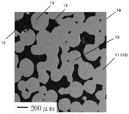
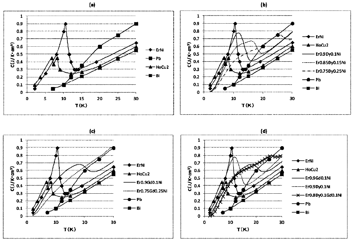
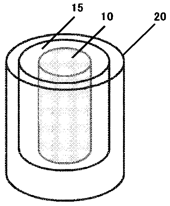

Image

  • Cooling storage material and method for producing same, cooling storage device, and refrigerating machine
  • Cooling storage material and method for producing same, cooling storage device, and refrigerating machine
  • Cooling storage material and method for producing same, cooling storage device, and refrigerating machine

Examples


Embodiment 1~8、 comparative example 1~3

[0131] Manufacture of HoCu using known atomization method 2 Particles, for the obtained HoCu 2 The particles passed through sieves of 100 μm and 300 μm (Examples 1 to 5, Comparative Examples 1 and 3) or sieves of 200 μm and 400 μm (Examples 6 to 8, Comparative Example 2) to remove fine particles and coarse particles. Thus, raw material particles having particle sizes and particle size distributions shown in Table 1 below were obtained. Perform DTA (differential thermal analysis) of the obtained raw material particles to determine HoCu 2 The melting point of the particles.

[0132] Next, a quartz tube with an inner diameter of 29.8 mm was used as a mold for forming a sintered body, and 200 g of raw material particles were filled therein, charged in a heat treatment furnace, and then sintered in an argon atmosphere. Thus a sintered body was obtained. The sintering temperature and sintering time are shown in Table 1. The sintering temperature is set so as to be 99% or less o...

reference example 1

[0148] Manufacture HoCu with the same method as embodiment 1 2 Particles were obtained to obtain raw material particles having particle diameters and particle size distributions shown in Table 1 below. The resulting raw material particles are filled to the inner diameter without sintering In the tube 31 made of plastic. In this filling, use felt with high fluidity (i.e., low pressure loss) as a filter, and a metal mesh as a support to insert the pipe 31 together, then throw 200 g of the above-mentioned raw material particles into the top to fill, and then fill the filled raw material particles Insert the same felt and metal mesh as above, and keep a pair of felts sandwiching the raw material particles. The above-mentioned pressure loss was measured with the raw material particles filled in this way. In addition, the porosity in this case was calculated by obtaining the apparent volume of the filling part of the raw material particles from the distance between the felts and...


PUM

PropertyMeasurementUnit
voidageaaaaaaaaaa

Abstract

Provided are: a cooling storage material of which the filling rate can be improved and falls within a proper range, and which can facilitate the reduction in pressure loss of a refrigerant gas in a cooling storage device; and a method for producing the cooling storage material. The cooling storage material according to the present invention comprises a sintered product of grains each containing arare earth element, wherein the porosity of the sintered product is 30 to 40%. The method for producing a cooling storage material according to the present invention comprises a step of sintering rawmaterial grains each containing a rare earth element, wherein the raw material grains have a D50 value of 100 to 320 Mum and a D90 / D10 ratio of 1.5 to 2.5 (wherein the terms "D10", "D50" and "D90" respectively represent average grain diameters corresponding to 10%, 50% and 90% in the total number of the grains in a grain size distribution curve).

Description

technical field [0001] The invention relates to a cold storage material, a manufacturing method thereof, a cold storage device and a refrigerator. Background technique [0002] At present, superconducting magnets have been or are being practically used in superconducting MRI (magnetic resonance imaging) devices that take tomographic images in the medical field, maglev trains, superconducting electric energy storage devices (SMES), and the like. Among them, superconducting magnets must be cooled to an extremely low temperature of 4.2K (approximately -269°C), which is the boiling point of liquid helium (He), but liquid helium is expensive and requires advanced technology to operate, so high-performance compact refrigerators are currently being developed Machine as a cooling means instead of liquid helium. As a small refrigerator that has been put into practical use, for example, a small helium refrigerator (ie, a GM refrigerator) of the Gifford-McMahon type is known. [0003...

Claims


Application Information

Patent Timeline
Patent Type & Authority Applications(China)
IPC IPC(8): C09K5/14F25B9/00F28D20/00
CPCC09K5/14F25B9/00F28D2020/006F28F2255/18F25B9/145F25B2309/1415
Inventor 栗岩贵宽松本恭知
Owner SANTOKU CORP
Learn More