Multi-zero point broadband filtering antenna based on radiation cancellation

A filter antenna and broadband technology, applied in the field of multi-zero broadband filter antenna, to achieve the effect of wide bandwidth, small cost and weight, and reduced volume

Active Publication Date: 2019-08-06
SOUTH CHINA UNIV OF TECH
View PDF6 Cites 9 Cited by
  • Summary
  • Abstract
  • Description
  • Claims
  • Application Information

AI Technical Summary

Problems solved by technology

The design methods of filter antennas are mainly divided into two categories: one method is the integrated design of the filter and the antenna, and the antenna is used as the last stage of the filter to resonate, but there is still insertion loss in the system

Method used


Image

  • Multi-zero point broadband filtering antenna based on radiation cancellation
  • Multi-zero point broadband filtering antenna based on radiation cancellation
  • Multi-zero point broadband filtering antenna based on radiation cancellation

Examples


Embodiment 1

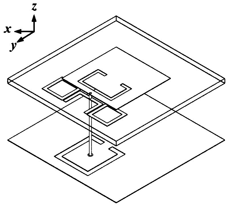
[0033] A multi-zero broadband filter antenna based on radiation cancellation, which is composed of a layer of dielectric substrate and a layer of metal floor, and adopts the method of probe feeding. The X-axis direction of the dielectric substrate is the vertical direction, and the Y-axis direction is the horizontal direction. , the origin is the center point of the dielectric substrate, and the direction of the XY coordinate system mentioned in this embodiment is subject to the accompanying drawings.

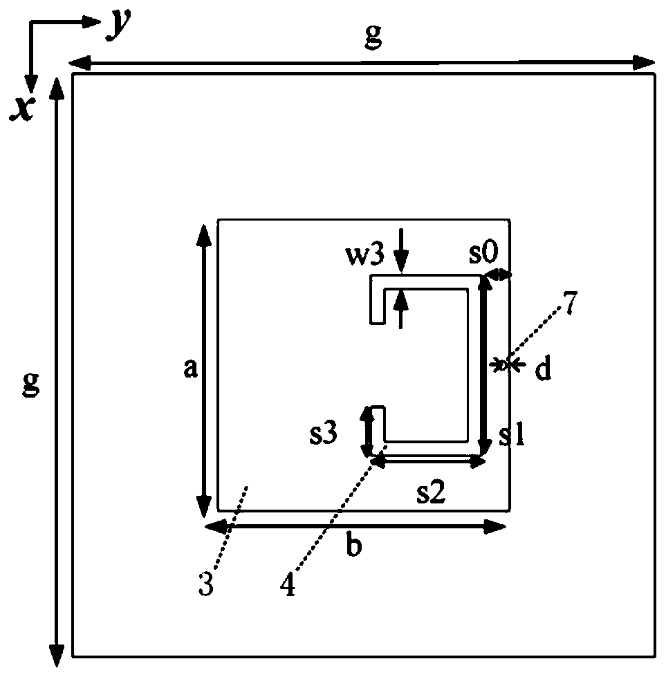
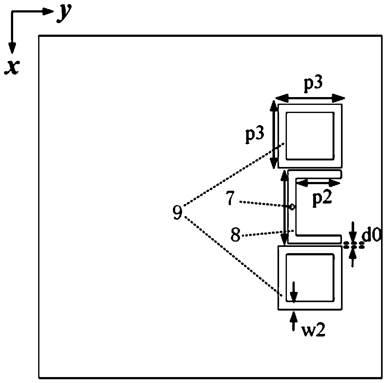
[0034] Such as figure 1 As shown in Figure 2(a), Figure 2(b), Figure 2(c) and Figure 2(d), it includes a dielectric substrate 1, a coaxial feed structure and a metal floor 2, and the metal floor is located below the dielectric substrate, There is air between the metal floor and the dielectric substrate for a certain distance, a metal radiation patch 3 is arranged on the upper surface of the dielectric substrate, a U-shaped branch is arranged on the lower surface of the dielectr...

Embodiment 2

[0056] As shown in Fig. 5(a), Fig. 5(b), Fig. 5(c) and Fig. 5(d), a multi-null broadband filter antenna based on radiation cancellation, the present embodiment adopts a differential feeding method, and the The coaxial feed structure includes two metal probes with the same structural size, and the two metal probes are symmetrically fed from the bottom of the metal floor to the metal radiation patch with respect to the X axis, and the metal probes share the center of the circular hole etched on the metal floor. The upper surface of the metal radiation patch is etched with two open ring-shaped gaps with the same structural size, and the lower surface is provided with two U-shaped branches with the same structural size. Two defective ground structures with the same structural size are etched on the metal floor. Two open rings The structures of the two U-shaped slits, the two U-shaped branches and the two defects are all symmetrical about the X-axis, and other features are the same ...


PUM


Abstract

The invention discloses a multi-zero point broadband filtering antenna based on radiation cancellation, which comprises a dielectric substrate and a metal ground plate, wherein the metal ground plateis located below the dielectric substrate, the metal ground plate and the dielectric substrate are filled with air therebetween, the upper surface of the dielectric substrate is provided with a metalradiation patch, the metal radiation patch is etched with a split ring-shaped slit, the lower surface of the dielectric substrate is provided with a U-shaped branch, two sides of the U-shaped branch are symmetrically provided with hollow square rings, and the metal ground plate is etched with a defected ground structure. The multi-zero point broadband filtering antenna further comprises a coaxialfeed structure, wherein the coaxial feed structure includes a metal probe, the metal probe feeds from the bottom of the metal ground plate, vertically passes through the U-shaped branch and is connected with the metal radiation patch, and the connecting point is located between the split ring-shaped slit and the edge of the metal radiation patch. The antenna is simple in structure and reduces theloss of the feed part of the antenna. The antenna is more suitable for the design of a planar antenna array due to easy processing, low cost and small size, and is applied to large-scale production.

Description

technical field [0001] The invention relates to a filter antenna, in particular to a multi-null broadband filter antenna based on radiation cancellation. Background technique [0002] With the development of modern wireless communication technology, the communication system tends to be miniaturized, integrated, and multi-functional, which requires higher and higher requirements for the RF front-end circuit. In the wireless communication system, the main function of the filter is to realize the selection of the signal, filter out the noise outside the frequency band, and suppress the harmonics, etc. Generally speaking, antennas and filters are designed independently, and then cascaded directly through transmission lines or matching circuits to coordinate work, but discrete designs require additional circuits for impedance matching, which will inevitably increase the size of the entire system, thus Additional transmission loss is generated, which has a great impact on the rad...

Claims


Application Information

Patent Timeline
Patent Type & Authority Applications(China)
IPC IPC(8): H01Q1/38H01Q1/48H01Q1/50H01Q15/00
CPCH01Q1/38H01Q1/48H01Q1/50H01Q15/0053
Inventor 杨琬琛张迎琪车文荃薛泉廖绍伟陈璐
Owner SOUTH CHINA UNIV OF TECH
Why Eureka
Try Eureka