High-pressure exhaust gas medium-pressure side introduction system based on two-stage turbocharger

A technology of turbocharger and introduction system, applied in charging system, exhaust gas recirculation, machine/engine, etc., can solve the problems of difficult layout of low-pressure EGR system, slow transient response speed, short circuit, etc., to reduce blockage Possibilities of particulate traps, high transient response speed, effect of short EGR loop

Pending Publication Date: 2019-08-13
TIANJIN UNIV
View PDF0 Cites 1 Cited by
  • Summary
  • Abstract
  • Description
  • Claims
  • Application Information

AI Technical Summary

Problems solved by technology

These two EGR technologies use different exhaust gas introduction methods, and have their inherent advantages and disadvantages and the range of suitable operating conditions: for high-pressure EGR, the circuit is short and the transient response is fast, but the supercharged intake air under high load The pressure is higher than the exhaust pressure before the vortex, and it is difficult to introduce EGR simply by opening the EGR valve, so high-pressure EGR is suitable for use in low-load conditions; The pressure before the vortex is smaller, the engine pumping loss is smaller, and it is easy to introduce exhaust gas to generate a large EGR rate. However, because the gas is taken after the after-treatment device, it has the disadvantages of difficult layout, long circuit and small pressure difference, resulting in The transient response speed is slow, and the engine emission is difficult to meet the requirements during the response period
[0004] To sum up, in order to meet the increasingly stringent regulatory requirements, it is necessary to solve the problems of difficult layout of the existing low-pressure EGR system and difficulty in introducing exhaust gas under heavy load of the high-pressure EGR system

Method used


Image

  • High-pressure exhaust gas medium-pressure side introduction system based on two-stage turbocharger

Examples


Embodiment Construction

[0020] In order to make the above-mentioned purposes, features and advantages of the present invention more obvious and understandable, the specific implementation modes of the present invention will be described in detail below in conjunction with the accompanying drawings, so that the above-mentioned and other purposes, features and advantages of the present invention will be clearer. In the drawings, the drawings are not intentionally drawn to scale, emphasis is placed on illustrating the gist of the invention. The present invention will be further described below in conjunction with the accompanying drawings.

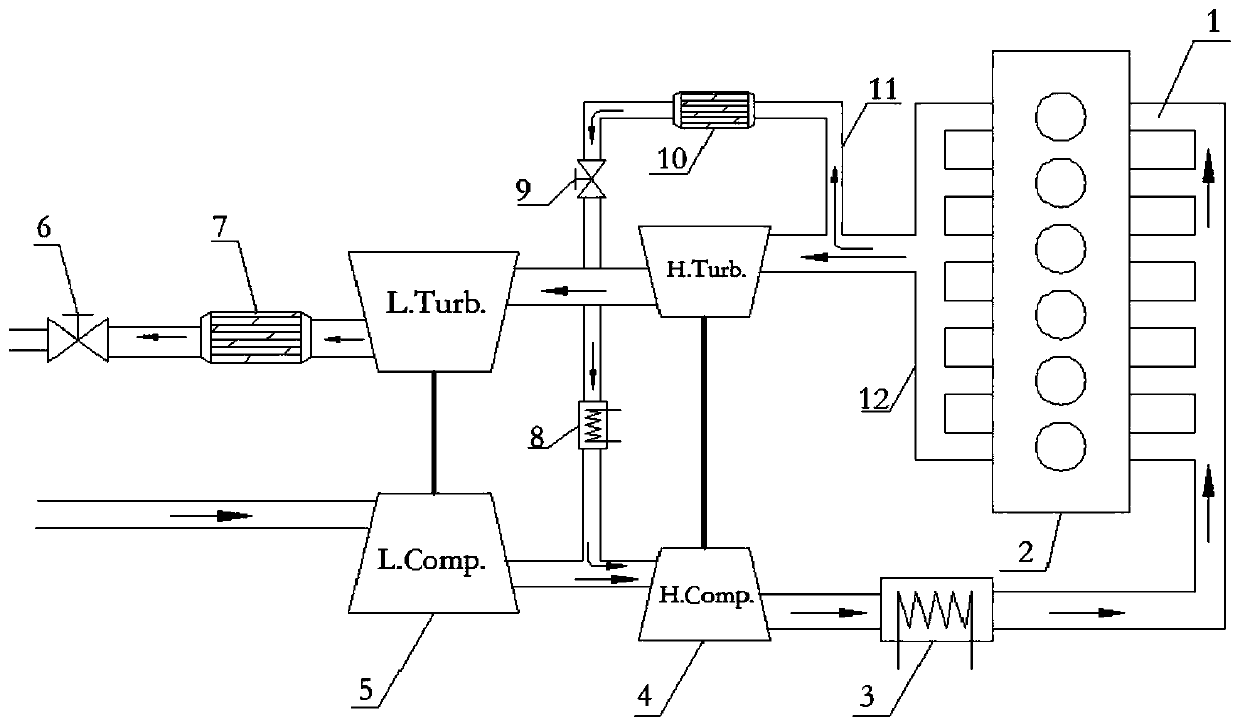
[0021] Such as figure 1 As shown, the present invention is based on a high-pressure exhaust gas middle-pressure side introduction system of a two-stage turbocharger, including an engine 2, a high-pressure stage turbocharger 4 and a low-pressure stage turbocharger 5, and the engine 2 is connected with an intake manifold 1 and an exhaust manifold 12, the intake manif...


PUM


Abstract

The invention discloses a high-pressure exhaust gas medium-pressure side introduction system based on a two-stage turbocharger. The high-pressure exhaust gas medium-pressure side introduction system comprises an engine, a high-pressure stage turbocharger and a low-pressure stage turbocharger, wherein the engine is connected with an intake manifold and an exhaust manifold; the high-pressure stage turbocharger comprises a high-pressure stage exhaust gas turbine and a high-pressure stage gas compressor, and the low-pressure stage turbocharger comprises a low-pressure stage exhaust gas turbine anda low-pressure stage gas compressor; the intake manifold is connected with an intake pipeline, and the exhaust manifold is connected with an exhaust pipeline; the intake pipeline is provided with thelow-pressure stage gas compressor, the high-pressure stage gas compressor and an intake intercooler, and the exhaust pipeline is provided with the high-pressure stage exhaust gas turbine, the low-pressure stage exhaust gas turbine, a postprocessor and a back pressure valve; a high-pressure EGR pipeline is connected between an inlet of the high-pressure stage exhaust gas turbine and an inlet of the high-pressure stage gas compressor; and the high-pressure EGR pipeline is provided with an EGR cooler, an EGR valve and a particulate matter catcher. The high-pressure exhaust gas medium-pressure side introduction system can expand the introduction range of EGR rate, have a high transient response speed, improve the efficiency of the engine, and reduce the emission.

Description

technical field [0001] The invention belongs to the technical field of diesel engine clean combustion, and more specifically relates to a high-pressure waste gas medium-pressure side introduction system based on a two-stage turbocharger. Background technique [0002] Modern emission regulations are becoming more and more stringent, and reducing engine exhaust emissions is an inevitable trend in the future, among which NOx and particulate matter emission controls are the most stringent. When the engine is working, NOx is likely to be produced in the high-temperature oxygen-enriched area when the fuel is burned in the cylinder. In order to reduce NOx emissions, the oxygen concentration and the maximum combustion temperature in the cylinder should be controlled. At present, technologies that can effectively reduce engine NOx emissions include exhaust gas recirculation technology (EGR), selective catalytic reduction (SCR) after-treatment technology and water-mixed combustion tec...

Claims


Application Information

Patent Timeline
Patent Type & Authority Applications(China)
IPC IPC(8): F02M26/08F02M26/35
CPCF02M26/08F02M26/35
Inventor 邬斌扬苏万华张志强刘一泽邓龙飞张仲王聪毋波
Owner TIANJIN UNIV
Why Eureka
Try Eureka