Ethane recycling method applied to rich gas and with self-cooling circulation

A recovery method and ethane technology, which is applied in the field of gas-rich ethane recovery, can solve the problems of high power consumption of external compressors, reduced gas phase volume of turbine expansion, and large refrigerant circulation volume, etc., to achieve improved ethane recovery rate, lower separation load, and reduced effect of storage and distribution devices

Active Publication Date: 2019-08-13
SOUTHWEST PETROLEUM UNIV
View PDF14 Cites 4 Cited by
  • Summary
  • Abstract
  • Description
  • Claims
  • Application Information

AI Technical Summary

Problems solved by technology

[0004] In the ethane recovery process for relatively rich gas, part of the dry gas recirculation process adopts primary cooling. The raw gas is pre-cooled in the cold box (E21) and then directly enters the low-temperature separator (V21). (V21) enters the middle of the demethanizer after condensing, resulting in an increase in the separation load of the demethanizer
One-stage separation makes the refrigerant need to cool all the raw material gas, the refrigerant circulation is large, and the energy consumption of the refrigeration compressor is high
The primary separation will also reduce the separated gas phase in the low temperature separator, and at the same time, a part of the separated gas phase in the low temperature separator needs to pass through the cold box (E22) to provide materials for the upper absorption section of the demethanizer (T21) to improve the recovery rate. Both reasons lead to the reduction of the gas phase volume of the turbine expansion, the decrease of the turbine expansion work, and the increase of the external compression work
The return flow of external dry gas will also increase the circulation of external gas, resulting in excessive power consumption of external compressors

Method used


Image

  • Ethane recycling method applied to rich gas and with self-cooling circulation
  • Ethane recycling method applied to rich gas and with self-cooling circulation

Examples


Embodiment 1

[0036] Such as figure 1 As shown, the composition and working conditions of 4 feed gas are as follows:

[0037] Raw material gas treatment scale: 500×104m 3 / d

[0038] Raw gas pressure: 5.0MPa

[0039] Raw gas temperature: 15°C

[0040] Dry gas output pressure: 5.0MPa

[0041] The raw gas composition is shown in Table 1

[0042] Table 1 Feed gas composition

[0043] composition N 2

CO 2

C 1

C 2

C 3

iC 4

c 4

iC 5

c 5

C 6

mol% 1.24 0.04 73.77 14.29 7.55 0.73 1.84 0.23 0.21 0.1

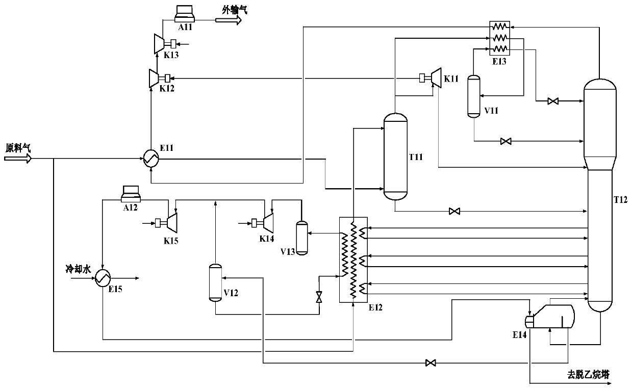
[0044] Such as figure 1 As shown, the present invention discloses an ethane recovery process suitable for rich gas with a refrigeration cycle,

[0045] The raw material gas (5000kPa, 15°C) is divided into two streams at the inlet, 22mol% of which is exchanged with the external gas to -35°C and then enters the lower part of the absorption tower (T11), and 78mol% is desorbed in the multi-strand cold box (E12). The 3 ...


PUM


Abstract

The invention discloses an ethane recycling method applied to rich gas and with self-cooling circulation, and relates to the technical field of natural gas treatment technologies. The raw gas is divided into two strands in an inlet, one strand is cooled through a pipe-shell heat exchanger and enters the bottom of an absorption tower, the other strand is cooled in a first cooling box and enters thetop of the absorption tower, a liquid-phase discharged material at the tower bottom of the absorption tower enters the middle of a demethanation tower, and a gas-phase discharged material at the tower top of the absorption tower enters a turbo expander and a second cooling box; and three strands of liquid-phase material is extracted from the side line of the lower part of the demethanation towerand enters the first cooling box for reheating to pre-cool the raw gas, the tower bottom condensation liquid of the demethanation tower is used as a mixture refrigerant of the self-cooling circulationto provide the cooling capacity for the first cooling box. By means of the ethane recycling method, the tower bottom condensation liquid of the demethanation tower is used as a mixture refrigerant inthe self-cooling circulation, the lower refrigerating temperature level can be provided, the process thermal integration degree is improved, higher ethane recycling under the rich gas condition is ensured, meanwhile, compared with a conventional ethane recycling process, the outer conveyed dry gas reflux is eliminated, and the power consumption of an outer conveying compressor can be significantly reduced.

Description

technical field [0001] The invention relates to the technical field of natural gas processing technology, in particular to an ethane recovery method suitable for rich gas with a self-cooling cycle. Background technique [0002] As domestic oil and gas fields gradually realize the huge economic value brought by ethane products, the research and development of efficient ethane recovery process has become particularly important. At present, the most typical ethane recovery process is the partial dry gas recirculation (RSV) process. When recovering ethane from relatively rich natural gas, refrigerant auxiliary refrigeration is usually required to increase the ethane recovery rate. Partial dry gas recirculation process suitable for gas-rich ethane recovery such as figure 2 As shown, the characteristics of the flow process are that after dehydration, the raw material gas enters the cold box (E21) for precooling and then enters the low-temperature separator (V21). The separated l...

Claims


Application Information

Patent Timeline
Patent Type & Authority Applications(China)
IPC IPC(8): F25J1/02F25J3/02F25J5/00
CPCF25J1/0258F25J1/0281F25J3/0238F25J5/00
Inventor 张世坚敬加强
Owner SOUTHWEST PETROLEUM UNIV
Why Eureka
Try Eureka