Biasing circuit for power amplifier and power amplifier

A technology for power amplifiers and bias circuits, applied in power amplifiers, amplifiers, high-frequency amplifiers, etc., can solve the problem of taking into account temperature compensation and linear compensation at the same time, affecting the gain of power amplifiers, good temperature compensation effects and linear compensation of power amplifiers Effect and other issues

Pending Publication Date: 2019-08-13
GUANGDONG UNIV OF TECH
View PDF0 Cites 18 Cited by
  • Summary
  • Abstract
  • Description
  • Claims
  • Application Information

AI Technical Summary

Problems solved by technology

However, if Figure 4 shown, with the capacitance to ground C 1 The increase of the capacitor value, because the signal of the main radio frequency link is more scattered, also affects the gain of the power amplifier to a certain extent, so the capacitance C to the ground 1 The capacitor value cannot be set too large
[0007] Due to the above-mentioned contradictions, t

Method used


Image

  • Biasing circuit for power amplifier and power amplifier
  • Biasing circuit for power amplifier and power amplifier
  • Biasing circuit for power amplifier and power amplifier

Examples


Embodiment Construction

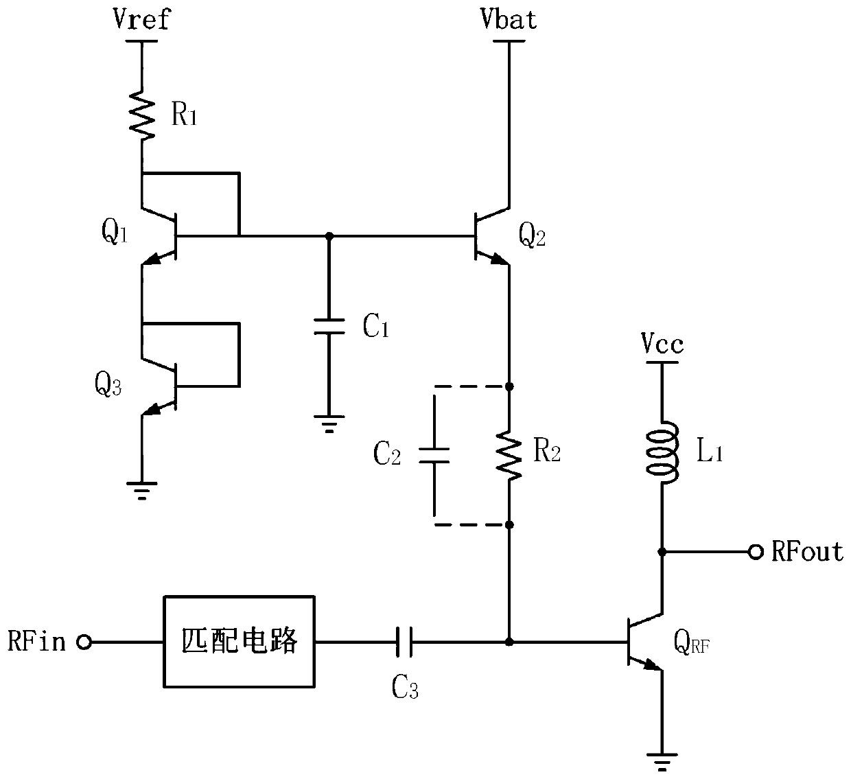
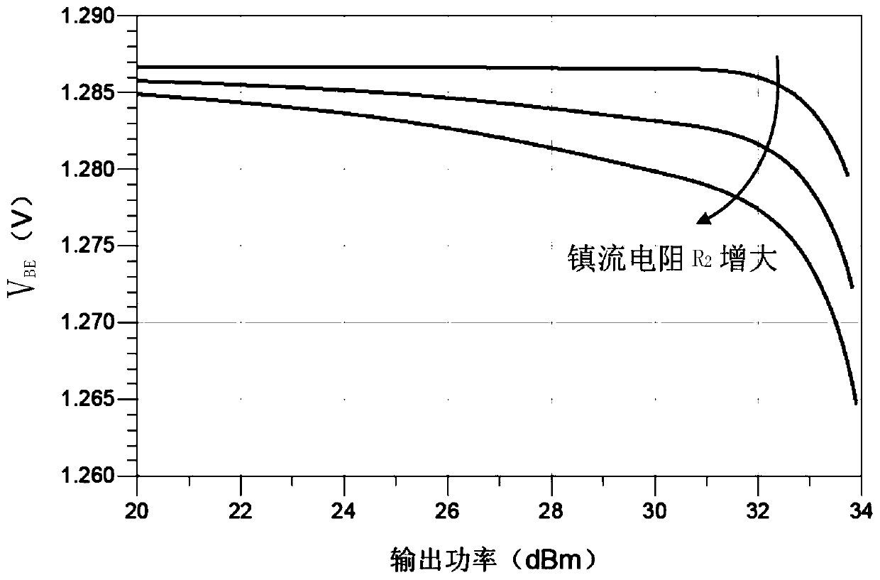
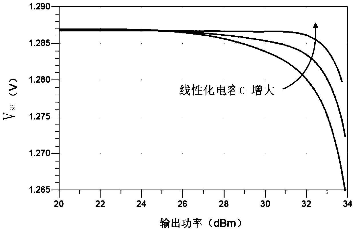
[0046] The core of the present invention is to provide a bias circuit and a power amplifier for power amplifiers, which are used to realize double improvement of thermal stability and linearity of the power amplifiers.

[0047] The following will clearly and completely describe the technical solutions in the embodiments of the present invention with reference to the accompanying drawings in the embodiments of the present invention. Obviously, the described embodiments are only some, not all, embodiments of the present invention. Based on the embodiments of the present invention, all other embodiments obtained by persons of ordinary skill in the art without making creative efforts belong to the protection scope of the present invention.

[0048] Figure 5 A circuit diagram of the first bias circuit for a power amplifier provided by an embodiment of the present invention; Figure 6 A circuit diagram of a Wilson current mirror provided by an embodiment of the present invention; ...


PUM


Abstract

The invention discloses a biasing circuit for a power amplifier. within order to solve the problem that contradiction among the temperature compensation effect, the linearization effect and the signalintegrity in the bias circuit in the prior art, a current negative feedback circuit is composed of a ballast resistor, a first transistor, a second resistor, a third resistor, a current mirror and asecond transistor, compensation is carried out in a manner of reducing current flowing through a ballast resistor, and a self-adaptive temperature negative feedback effect is achieved; therefore, whenthe resistance value of the ballast resistor is increased to enhance the temperature compensation effect, the linearity of the radio frequency power tube is not influenced, the contradiction betweenthe temperature compensation and the linear compensation is eliminated, the contradiction between the linear compensation and the signal integrity is further avoided, and the power amplifier realizesthe double improvement of the thermal stability and the linearity. The invention also discloses a power amplifier which has the above beneficial effects.

Description

technical field [0001] The invention relates to the technical field of radio frequency integrated circuits, in particular to a bias circuit and a power amplifier for a power amplifier. Background technique [0002] The power amplifier (Power Amplifier, PA) is one of the key units in the wireless communication link. Its function is to amplify the modulated signal carrying useful information to a certain power and radiate it through the antenna. The output capability, linearity and Efficiency is largely determined by the power amplifier. In the high-frequency monolithic microwave integrated circuit (MMIC) used in mobile phones, the Heterojunction Bipolar Transistor (HBT) process is mostly used for manufacturing. For the current mainstream GaAsHBT process, since the thermal conductivity of gallium arsenide is very low, and will continue to decrease with the increase of temperature, when the power amplifier works in a large signal state, considerable power dissipation will occu...

Claims


Application Information

Patent Timeline
IPC IPC(8): H03F1/30H03F1/32H03F3/19H03F3/21H03F3/24H03F3/45
CPCH03F1/302H03F1/3211H03F3/19H03F3/211H03F3/245H03F3/4508H03F2200/447H03F2200/451
Inventor 彭林章国豪
Owner GUANGDONG UNIV OF TECH
Why Eureka
Try Eureka