Sub-nanoscale mandrel for manufacturing grazing-incidence reflection lens by replication and manufacturing process

A sub-nano-scale, manufacturing process technology, applied in the field of ultra-smooth sub-nano-scale mandrel manufacturing process, can solve the problems of large-area collection of X-rays, difficult surface roughness of nickel-phosphorus alloys, low X-ray reflection efficiency, etc. , to achieve the effect of ensuring surface quality, reducing processing costs and ensuring precision

Active Publication Date: 2019-08-16
BEIJING INST OF CONTROL ENG
View PDF7 Cites 5 Cited by
  • Summary
  • Abstract
  • Description
  • Claims
  • Application Information

AI Technical Summary

Problems solved by technology

However, the roughness of the mandrel processed by this method is at the nanometer level, which is still far from the sub-nanometer level. The X-ray reflection efficiency is low, and it is difficult to meet the large-area collection of X-rays.
[0005] The surface of the grazing-incidence precision mandrel is composed of a combination of high-steep paraboloid and hyperboloid or a paraboloid alone, which is difficult to process and manufacture. Pore defects are prone to appear on the surface after electroless nickel-phosphorus alloy plating, and the nickel-phosphorus alloy surface of this type of surface is rough. It is very difficult to reach the sub-nanometer level. The better the roughness of the mandrel, the better the X-ray collection effect of the reflective lens and the higher the angular resolution. Moreover, the structure of the mandrel directly affects the surface accuracy of the mandrel and the quality of the subsequent reflector. The above problems are the processing difficulties of this process route

Method used


Image

  • Sub-nanoscale mandrel for manufacturing grazing-incidence reflection lens by replication and manufacturing process
  • Sub-nanoscale mandrel for manufacturing grazing-incidence reflection lens by replication and manufacturing process
  • Sub-nanoscale mandrel for manufacturing grazing-incidence reflection lens by replication and manufacturing process

Examples


Embodiment

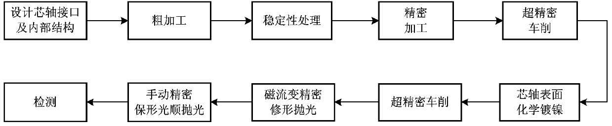
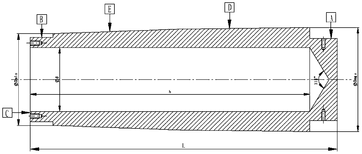
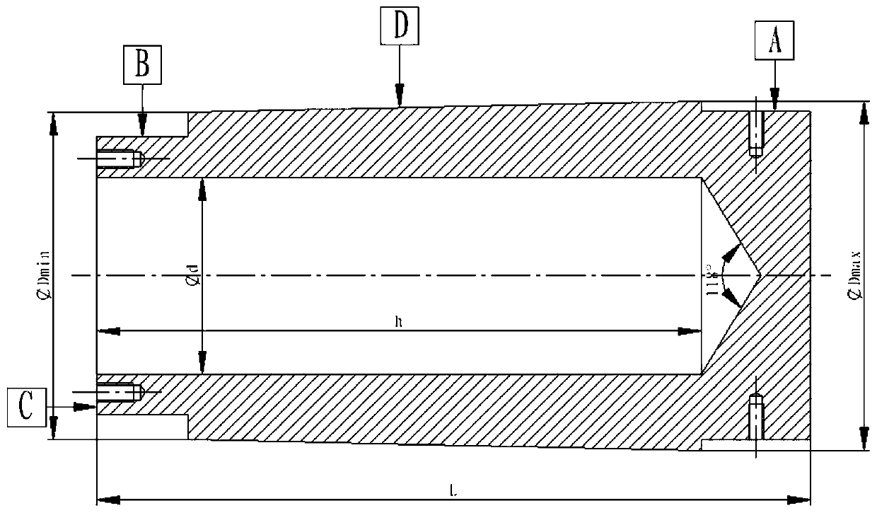
[0072] Using this manufacturing process to process a certain size of double reflection grazing incidence precision mandrel, as attached Figure 2b ) As shown in the figure, the maximum diameter of the mandrel is D max =114mm, minimum diameter D min =100.524mm, total length of mandrel L=330mm, diameter of blind hole d=65mm, depth of blind hole h=300mm. After mandrel rough machining, stability treatment, precision machining, ultra-precision turning, then electroless nickel plating with a thickness of 80-90μm, ultra-precision turning to a surface roughness of 9nm, and then magnetorheological modification and polishing, the surface roughness can reach 0.75-0.9nm, and finally manual conformal smooth polishing.

[0073] Implementation effect: After processing, the precision of the grazing incidence mandrel can reach 1 μm, and the surface roughness of the white light interferometer can reach RMS 0.4nm. At the same time, the mandrel has been used as a mold to replicate and process u...


PUM

PropertyMeasurementUnit
thicknessaaaaaaaaaa
thicknessaaaaaaaaaa
thicknessaaaaaaaaaa

Abstract

The invention relates to a sub-nanoscale mandrel for manufacturing a grazing-incidence reflection lens by replication and a manufacturing process. The mandrel comprises a lens replication section andchuck sections on two end faces of the lens replication section, wherein a blind hole is formed in the mandrel and runs through the chuck section at a small end and the lens replication section alongthe axis of the mandrel; a uniform clamping interface used universally in all steps of the manufacturing process is arranged at the chuck section at one end of the mandrel in the direction parallel tothe axis of the mandrel; and a uniform clamping interface used universally in all the steps of the manufacturing process is arranged at the chuck section at the other end of the mandrel in the direction perpendicular to the axis of the mandrel. The manufacturing process comprises the following steps: performing rough machining on the mandrel according to the interfaces of the two chucks of the mandrel and the internal structure of the mandrel; performing high- and low-temperature treatment, precision turning and ultra-precision turning in sequence; plating the mandrel with a nickel-phosphorusalloy; performing ultra-precision turning again; and performing magneto-rheological shape-correcting polishing and manual shape-preserving polishing to complete the machining of the grazing-incidencesub-nanoscale mandrel. The manufacturing process ensures the sub-nanoscale surface accuracy of the mandrel and can improve the success rate of the follow-up demolding of the reflection lens.

Description

technical field [0001] The invention relates to the field of ultra-precision machining, in particular to a manufacturing process for duplicating an ultra-smooth sub-nanometer mandrel for manufacturing a grazing incident reflector. Background technique [0002] In recent years, X-ray astronomical observation and X-ray pulsar navigation have gradually attracted the attention of various countries. At present, paraboloid-hyperboloid double reflection (Wolter-I) and paraboloid single reflection grazing incidence optical systems are widely used to collect X-rays. Taking two reflections as an example, the principle is that each lens layer of the optical lens is composed of a coaxial and confocal parabolic primary lens and a hyperboloid secondary lens, and the X-ray photons incident parallel to the optical axis are reflected by the primary mirror and the secondary mirror successively After that, it is converged to an area of ​​only tens of mm 2 On the focal plane, the effective det...

Claims


Application Information

Patent Timeline
Patent Type & Authority Applications(China)
IPC IPC(8): B23P15/00
CPCB23P15/00
Inventor 杨春雷黎月明杨健孙慧丽徐天达武胜勇申坤邓楼楼左富昌武宏宇张青张强王品杨春强
Owner BEIJING INST OF CONTROL ENG
Why Eureka
Try Eureka