A self-compensating laser liquid level measurement system

A liquid level measurement and self-compensation technology, which is applied in liquid/fluid solid measurement, measuring devices, liquid level indicators, etc., can solve problems such as angle errors, and achieve the effect of fewer external components and accurate and efficient measurement methods

Inactive Publication Date: 2020-07-31
HARBIN UNIV OF SCI & TECH
View PDF5 Cites 0 Cited by
  • Summary
  • Abstract
  • Description
  • Claims
  • Application Information

AI Technical Summary

Problems solved by technology

[0004] The purpose of the present invention is to solve the problem of the angle error between the laser beam direction and the vertical direction of the measured liquid surface caused by the deflection of the laser liquid level measuring device, and to provide a self-compensating laser liquid level measuring system

Method used


Image

  • A self-compensating laser liquid level measurement system
  • A self-compensating laser liquid level measurement system
  • A self-compensating laser liquid level measurement system

Examples


specific Embodiment approach 1

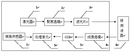
[0017] DETAILED DESCRIPTION OF THE PREFERRED EMBODIMENT 1. A self-compensating laser liquid level measurement system, which includes a laser (1), a focusing lens (2), an optical filter (3), an imaging lens (4), an industrial camera (CCD) (5), a processing unit (6), inclination sensor (7), such as figure 1 shown. The inclination sensor (7) is installed in the laser liquid level measuring device, and is used for measuring the deflection angle of the laser liquid level measuring device. The laser (1) emits laser light, and the laser beam passes through the focusing lens (2) to form a point light source, and then irradiates on the surface of the measured liquid surface (8) to form a light spot, which is imaged on the industrial camera (CCD) (5). Image processing is carried out in the unit (6), the centroid of the light spot is identified, the displacement of the light spot on the CCD (5) is calculated, and the displacement of the measured liquid level (8) is calculated according ...

specific Embodiment approach 2

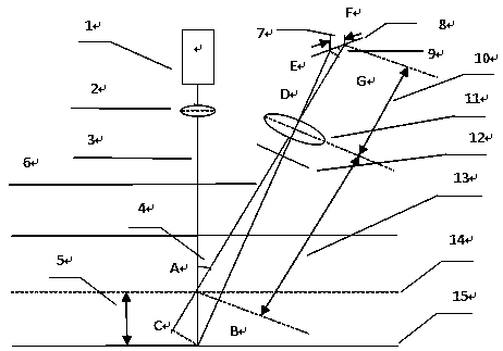
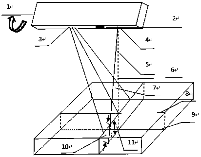
[0018] Specific implementation mode two, such as image 3 As shown, when the laser liquid level measuring device is deflected (outward along the vertical paper surface), the working principle is:

[0019] 1. The inclination sensor (2) is installed in the laser liquid level measuring device (1), and is used to measure the deflection angle of the laser liquid level measuring device (1). The light beam (6) emitted by the laser (4) is perpendicular to the groove surface (9), and at this time, the CCD (3) detects that the light spot is at position 1 on the CCD;

[0020] 2. When the laser liquid level measuring device (1) occurs such as figure 2 When deflecting in the indicated direction (outward direction along the vertical paper surface), the angle sensor (2) detects that the angle between the direction of the deflected laser beam (7) and the vertical direction of the measured liquid surface (8) is θ( 5), that is, the deflection angle of the laser liquid level measuring device ...


PUM


Abstract

A self-compensating laser liquid level measurement system relates to the field of metal liquid level measurement. Solve the measurement error problem caused by the installation or deflection of the laser liquid level measurement device during liquid level measurement. The invention includes: an inclination sensor, a laser, a focusing lens, a filter, an imaging lens, an industrial camera and a processing unit. The inclination sensor detects the angle between the beam direction and the vertical direction of the measured liquid surface; the laser emits laser light to the measured liquid surface and forms a spot; the focusing lens focuses the beam to form a point light source; the optical filter filters the interfering light source; the light passes through the imaging lens Imaging on the industrial camera; the industrial camera detects the light spot; when the distance between the laser and the measured liquid level changes, the light spot is imaged at different positions on the industrial camera, and the processing unit obtains the displacement of the measured liquid level through the imaging relationship. The invention can make up for the measurement error caused by the angle change between the beam direction of the laser and the vertical direction of the measured liquid surface, and can obtain the actual change and displacement of the measured liquid surface. The method is accurate and efficient.

Description

technical field [0001] The invention relates to solving the metal liquid level measurement error problem caused by the installation or deflection of a laser liquid level measuring device, and belongs to the field of process control in the metallurgical industry. Background technique [0002] As a classic non-contact measurement method, laser triangulation has many advantages such as simple structure, fast measurement speed, high resolution, strong anti-interference ability and real-time processing. However, in metallurgy, due to the high temperature of the metal liquid, the use of contact measurement methods can easily cause damage to the measurement equipment, so non-contact measurement methods are used. However, due to the installation process, mechanical vibration and other reasons, the laser liquid level measurement device is deflected, resulting in an angle between the direction of the laser beam and the vertical direction of the measured liquid surface, resulting in an...

Claims


Application Information

Patent Timeline
Patent Type & Authority Patents(China)
IPC IPC(8): G01F23/292G01F23/00
CPCG01F23/292G01F23/802
Inventor 许景波马文博
Owner HARBIN UNIV OF SCI & TECH
Why Eureka
Try Eureka