Permanent magnet transmission device with water-cooled heat dissipation device

A technology of permanent magnet transmission and heat dissipation device, which is applied in the direction of cooling/ventilation device, permanent magnet clutch/brake, electromechanical device, etc., which can solve the problem of poor adaptability and maintenance-free performance, backward system adjustment mode, and mismatched system Reasonable and other issues, to achieve the effect of preventing heat conduction, low maintenance and maintenance costs, and improving transmission efficiency

Inactive Publication Date: 2019-08-16
沈阳嘉和航空机械制造股份有限公司
View PDF0 Cites 0 Cited by
  • Summary
  • Abstract
  • Description
  • Claims
  • Application Information

AI Technical Summary

Problems solved by technology

[0003] Domestic motors and driven equipment generally have unreasonable system matching, the phenomenon of "big horse-drawn carts" is serious, and the equipment operates at low load for a long time; the system adjustment method is backward, most fans and pumps are adjusted by mechanical throttling, and the efficiency ratio is adjusted. speed way lower than 30%
[0004] At present, the commonly used transmission device has the adaptability and maintenance-free performance in harsh working environments, and the transmission of harmonic interference has low performance. The resonance effect is obviously not conducive to kinetic energy transmission and energy saving and environmental protection.

Method used


Image

  • Permanent magnet transmission device with water-cooled heat dissipation device
  • Permanent magnet transmission device with water-cooled heat dissipation device

Examples


Embodiment Construction

[0017] The present invention will be further described in detail below in conjunction with the accompanying drawings and embodiments.

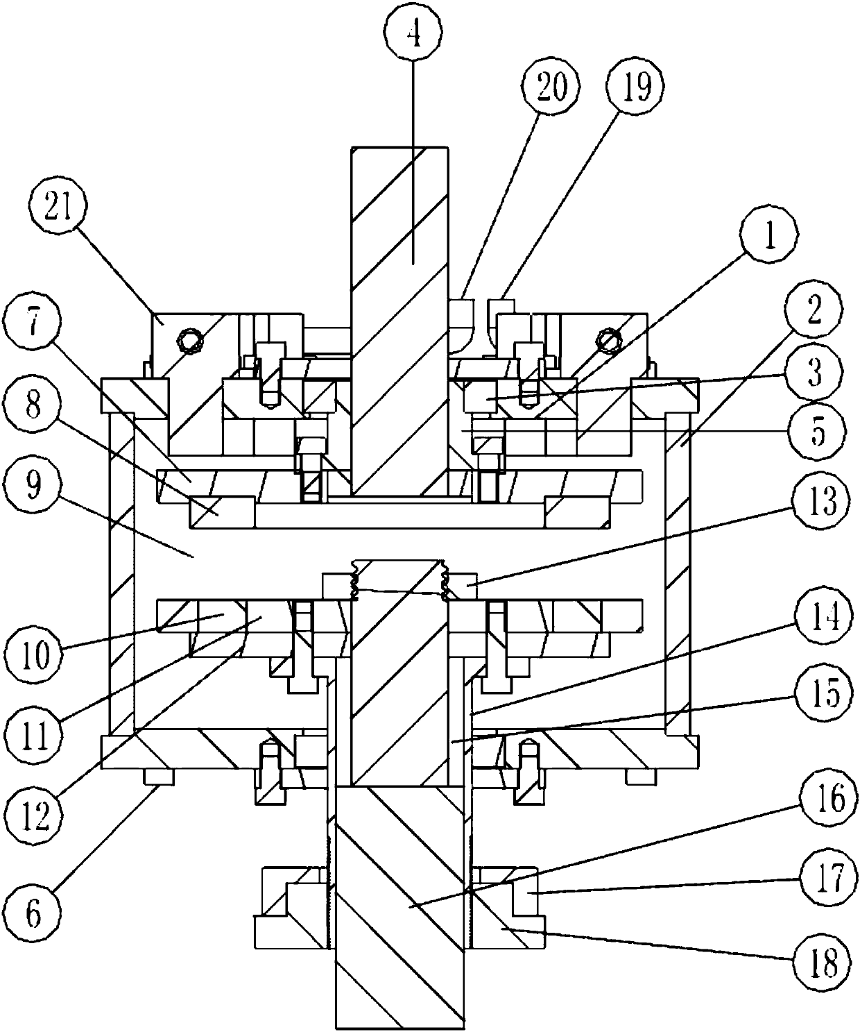
[0018] Such as figure 1 Shown is the device structure diagram of the present invention.

[0019] A water-cooled magnetic transmission energy-saving device, which includes active copper rotor components 7, 8 mounted on the drive shaft 4, permanent magnet rotors 10, 11, 12 assemblies mounted on the driven shaft 15, 16, and a lead screw adjuster 14, 17, 18. The active copper rotor is composed of a disc-shaped steel frame 7 and a copper conductive ring 8, and the copper conductive ring is installed on the surface of the steel plate. Permanent magnets 10 are inlaid on opposite surfaces of the permanent magnet rotor and the active copper rotor. There is an adjustable axial air gap 9 between the opposing surfaces of the active copper rotor and the permanent magnet rotor, and the two are coupled together through magnetic force. When the active cop...


PUM


Abstract

The invention relates to a permanent magnet transmission device with a water-cooled heat dissipation device. The permanent magnet transmission device comprises an active copper rotor component arranged on a driving shaft 4, permanent magnet rotor components arranged on driven shafts 15 and 16, and a screw rod regulator, wherein the active copper rotor component is formed by a disc-shaped steel frame 7 and a copper conducting ring 8, the surface of the steel plate is provided with the copper conducting ring; the opposite surfaces of the permanent magnet rotor components and the active copper rotor component are embedded with permanent magnets 10; the opposite surfaces of the active copper rotor component and the permanent magnet rotor components are spaced by an adjustable axial air gap 9,and the active copper rotor component and the permanent magnet rotor components are coupled through the magnetic force. When permanent magnet transmission device is loaded, the medium-high speed operation is required, and the advantage of replacing a frequency converter under the working condition that the power is more than 50KW is obvious; adaptability and maintenance-free performance in severeworking environments are high; the interference of the motor can be eliminated, and the working efficiency of the motor is improved; the vibration transmission between the motor and the load can be eliminated; the maintenance and repair cost is low; and the service life of each main part of the transmission system can be effectively prolonged.

Description

technical field [0001] The invention relates to the field of permanent magnet transmission, in particular to a permanent magnet transmission with a water-cooled heat sink. Background technique [0002] The permanent magnet transmission technology is not simply using the principle of magnets of the same sex repelling each other and opposite sexes attracting each other, it is the integration of transmission technology, material technology and manufacturing technology. Manufacturing technology in the 21st century will not only continue to manufacture machines and equipment operating under normal conditions, but also manufacture machinery and equipment operating in extreme environments. The products manufactured in the 21st century should be green products that are energy-saving, environmentally friendly, and friendly to people. Magnetic drive technology is just to adapt to this development trend came into being. With the continuous emergence of new technologies, new processes,...

Claims


Application Information

Patent Timeline
Patent Type & Authority Applications(China)
IPC IPC(8): H02K49/10H02K9/19
CPCH02K9/19H02K49/108
Inventor 孟凡琛刘永峰
Owner 沈阳嘉和航空机械制造股份有限公司
Why Eureka
Try Eureka