
Brake disc shell type lamination casting method and casting mold

A technology of casting molds and brake discs, which is applied in the direction of manufacturing tools, casting molding equipment, casting molds, etc., can solve the problems of huge production line equipment, declining product competitiveness, and insufficient response ability, so as to improve order adaptability and product performance The effect of improving and saving equipment investment costs

Inactive Publication Date: 2019-08-20
大连德原工业有限公司
View PDF6 Cites 4 Cited by
  • Summary
  • Abstract
  • Description
  • Claims
  • Application Information

AI Technical Summary

Problems solved by technology

[0002] The existing casting method for manufacturing brake discs with air ducts is made by green sand molding, and the appearance is made of green sand. However, the casting production steps of green sand are complicated, the production line equipment is huge, the cost is high, and the required area of ​​the factory building is large. Large, complex infrastructure and long construction period lead to a large amount of fixed costs for the factory, but cannot quickly increase production capacity, decline in the ability to accept orders, insufficient responsiveness to the market, increased costs, and decreased product competitiveness, etc.
There are many electric and hydraulic systems in the green sand automatic casting line, the operation cost and maintenance cost of the equipment are high, and once the equipment fails, the entire line will stop production
Micropowder additives such as bentonite and coal powder must be used in green sand casting, which pollutes the factory environment a lot, and the large amount of dust generated by the dust collection system puts pressure on the protection of the national and local environment.

Method used


Image

  • Brake disc shell type lamination casting method and casting mold
  • Brake disc shell type lamination casting method and casting mold
  • Brake disc shell type lamination casting method and casting mold

Examples


Embodiment Construction

[0026] The specific embodiment of the present invention will be further described in detail below in conjunction with the accompanying drawings.

[0027] It should be noted that, in the following specific embodiments, when describing the embodiments of the present invention in detail, in order to clearly show the structure of the present invention for the convenience of description, the structures in the drawings are not drawn according to the general scale, and are drawn Partial magnification, deformation and simplification are included, therefore, it should be avoided to be interpreted as a limitation of the present invention.

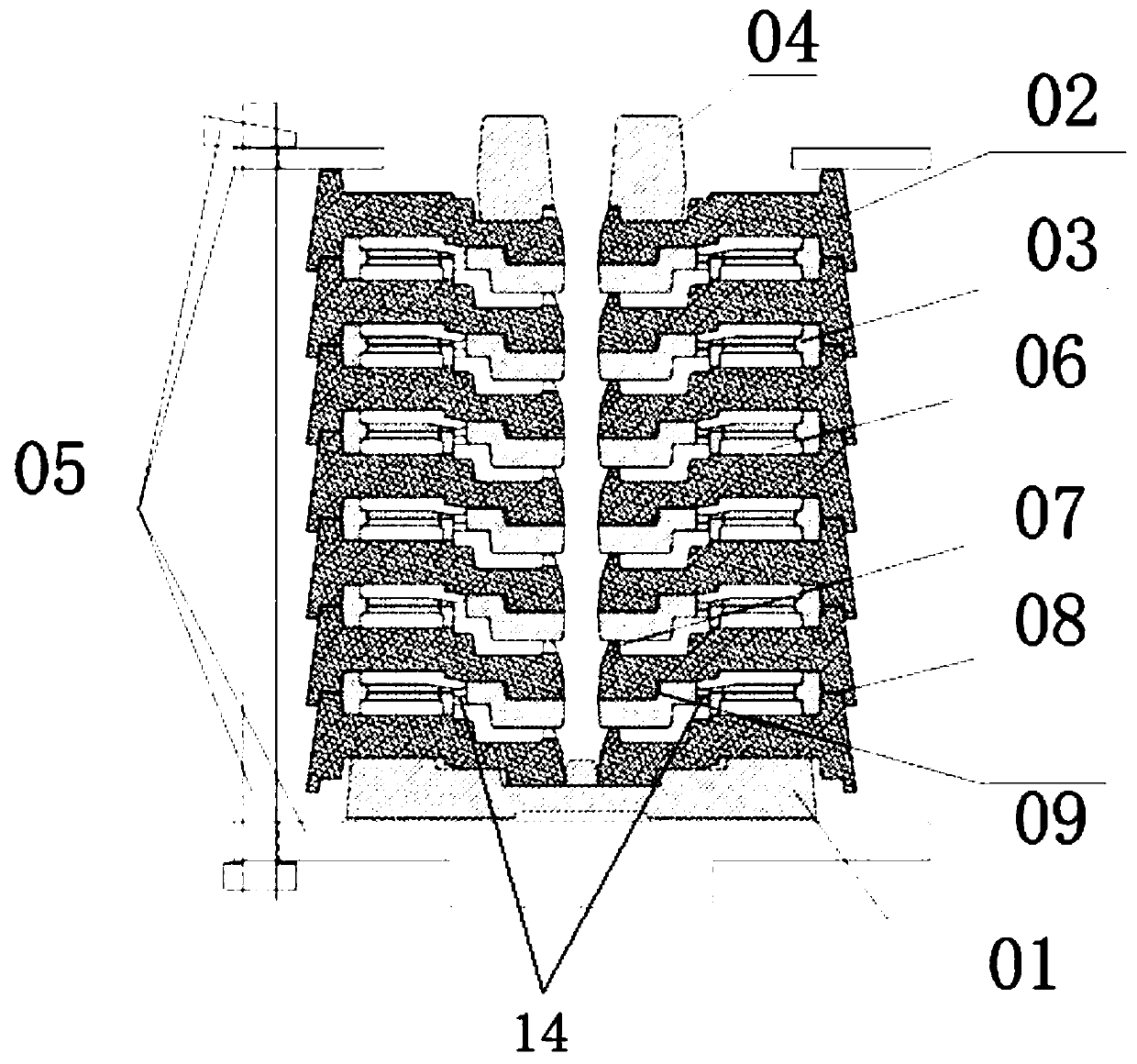
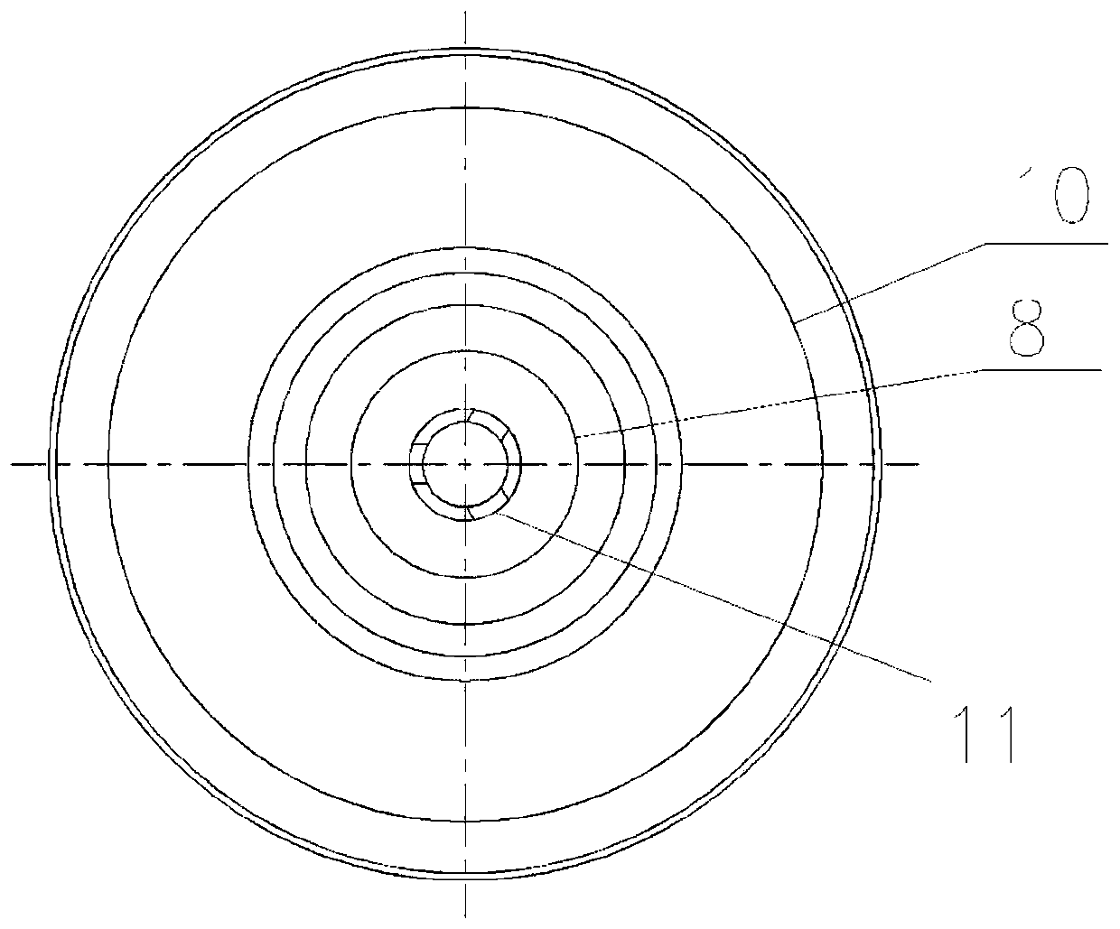
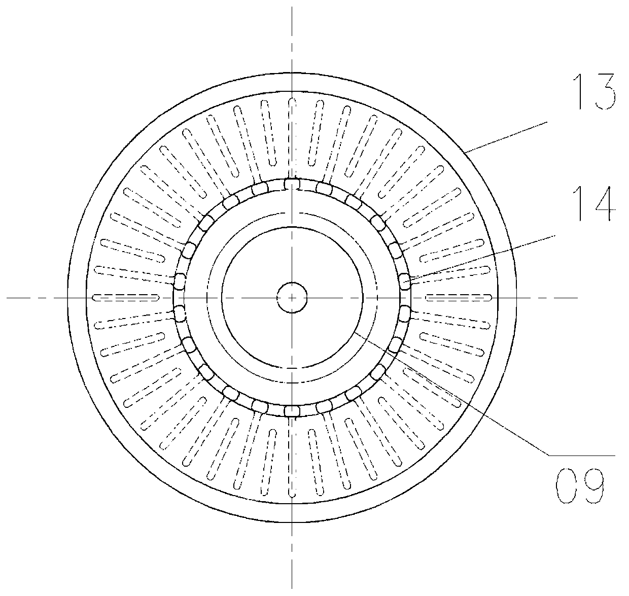
[0028] In the following specific embodiments of the present invention, please refer to Figure 1-Figure 4 , figure 1 It is a structural schematic diagram of a laminated casting mold for a brake disc shell with an air duct.

[0029] The stacked casting method of the brake disc shell with air duct of the present invention is divided into four steps ...


PUM


Abstract

The invention discloses a brake disc shell type lamination casting method and a casting mold. The brake disc shell type lamination casting method comprises the following four steps that S1, molding iscarried out, a precoated sand core-making mechanism is adopted as a casting mold made of precoated sand, the casting mold comprises a bottom plate sand core mold, a plurality of appearance sand coremolds and a gate cup sand core mold; S2, clamping laminated core is carried out, the bottom plate sand core mold, a plurality of sets of alternately overlapped outline sand core molds, the shape sandcore mold at the top end and the sprue cup sand core mold are clamped and assembled from bottom to top in sequence, after assembly is completed, and the mold is clamped by a clamp; S3, casting and cooling are carried out; and S4, the clamp is disassembled, the casting mold is removed, and a brake disc finished product is obtained. According to the brake disc shell type lamination casting method, awet mold sand molding technology adopted in the traditional casting process can be completely abandoned, so that the investment cost of a large amount of wet mold sand automatic molding line equipment is saved.

Description

technical field [0001] The invention relates to a casting process of a brake disc with an air duct, and more particularly relates to a brake disc shell type lamination casting method and a casting mold. Background technique [0002] The existing casting method for manufacturing brake discs with air ducts is made by green sand molding, and the appearance is made of green sand. However, the casting production steps of green sand are complicated, the production line equipment is huge, the cost is high, and the required area of ​​the factory building is large. Large, complex infrastructure and long construction period lead to a large amount of fixed costs for the factory, but cannot quickly increase production capacity, decline in the ability to accept orders, insufficient responsiveness to the market, increase in costs, and decline in product competitiveness. There are many electric and hydraulic systems in the green sand automatic casting line, the operation cost and maintenan...

Claims


Application Information

Patent Timeline
Patent Type & Authority Applications(China)
IPC IPC(8): B22C9/02B22C9/08B22C9/20B22C9/22
CPCB22C9/02B22C9/082B22C9/20B22C9/22
Inventor 吴德原
Owner 大连德原工业有限公司
Learn More