System and method for fused salt or heat transfer oil steam generation adopting in-pipe evaporation and avoiding external force for driving

A heat-conducting oil, no external force technology, applied in the field of molten salt or heat-conducting oil steam generation system, can solve the problems that affect the safe operation of the system, difficult to discharge clean, large temperature difference, etc., to reduce the risk of molten salt freezing and save high temperature material, effect of reducing shell thickness

Pending Publication Date: 2019-08-23
HANGZHOU BOILER GRP CO LTD
View PDF0 Cites 4 Cited by
  • Summary
  • Abstract
  • Description
  • Claims
  • Application Information

AI Technical Summary

Problems solved by technology

Because of the molten salt or heat transfer oil in the pipes of this type of system, it is not easy to discharge cleanly when the system is shut down and emptied, and it is easy to cause the molten salt to freeze in the evaporator pipe, which brings risks to the system
In addition, this type of evaporator has a large temperature difference between the inlet and outlet of molten salt (or heat transfer oil). For a large-capacity photothermal power station that uses molten salt as the heat-absorbing and heat-storing medium, the temperature difference between the inlet and outlet will reach about 100°C
This working condition brings serious challenges to the evaporator with U-shaped tube bundle and single tube plate structure, which will cause stress concentration on the tube plate of the evaporator, and long-term operation will cause cracks and leakage, which will affect the safe operation of the entire system

Method used


Image

  • System and method for fused salt or heat transfer oil steam generation adopting in-pipe evaporation and avoiding external force for driving

Examples


Embodiment Construction

[0023] The present invention will be further described below in conjunction with the accompanying drawings and specific embodiments.

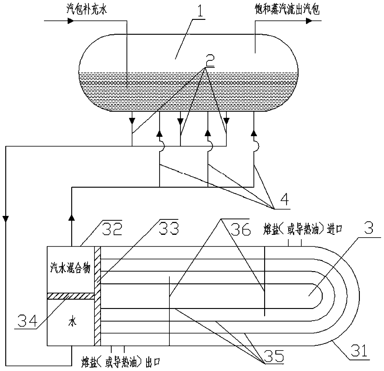
[0024] Such as figure 1 As shown, the present invention is a molten salt or heat conduction oil vapor generation system that evaporates without external force in the tube, including a steam drum 1 , a downcomer 2 , an evaporator 3 , and an upcomer 4 . The evaporator 3 further includes a shell 31 , a head 32 , a tube sheet 33 , a partition plate 34 , a tube bundle 35 , a baffle plate 36 and the like. The steam drum 1 is located above the evaporator 3 , and the steam drum 1 and the evaporator 3 are connected through the downpipe 2 and the uppipe 4 to form a system.

[0025] The outer side of the shell 31, the tube sheet 33 and the tube bundle 35 of the evaporator 3 is the shell side space; the inner side of the head 32, the tube sheet 33 and the tube bundle 35 is the tube side space; There are two parts, the water chamber and the steam-water mi...


PUM


Abstract

The invention relates to a system and method for fused salt or heat transfer oil steam generation adopting in-pipe evaporation and avoiding external force for driving. The steam generation system comprises a steam drum, a downcomer, an evaporator and a riser; the evaporator comprises a shell, a sealing head, a tube plate, a partition plate, a U-shaped tube bundle and a baffle plate; the steam drumis arranged above the evaporator, and the steam drum and the evaporator are connected into a whole through the downcomer and the riser; the inner side of the evaporator shell, the tube plate and theouter side of the U-shape tube bundle form a shell side space; the sealing head, the tube plate and the inner side of the U-shaped tube bundle form a tube side space; fused salt or heat transfer oil medium runs in the shell side space, and water/steam and water mixture medium runs in the tube side space; the space in the sealing head is divided into a water chamber and a steam-water mixing chamberby a partition plate, the water chamber is on the lower part and the steam-water mixing chamber is on the upper part; and the plurality of baffle plates are designed outside the U-shaped tube bundleto form a channel with a certain shape to guide fused salt or heat transfer oil to flow through the channel.

Description

technical field [0001] The invention relates to a system and method for generating molten salt or heat-conducting oil steam without external force for evaporation in a tube, and belongs to the fields of industrial heating and solar thermal power generation using special media. Background technique [0002] Molten salt has the characteristics of high boiling point, wide liquid phase temperature range, high specific heat capacity, and strong heat exchange capacity, so it is an ideal medium for heat transfer and heat storage. In recent years, molten salt has been widely used in industrial fields as a heat transfer and heat storage medium. Solar thermal power generation is a renewable energy with large capacity, high efficiency, wide distribution, clean and environmental protection, combined with molten salt energy storage, the technology has the characteristics of thermal and electrical decoupling, and the solar thermal unit can be flexibly adjusted according to the power grid ...

Claims


Application Information

Patent Timeline
Patent Type & Authority Applications(China)
IPC IPC(8): F22B1/06F22B1/16
CPCF22B1/06F22B1/16
Inventor 姚飞奇刘可亮应仁丽余红霞邹尚奇
Owner HANGZHOU BOILER GRP CO LTD
Why Eureka
Try Eureka