Simulation method based on collected laser shock data and strengthening quality control device

A technology of laser shock strengthening and laser shock, which is applied in the fields of electrical digital data processing, special data processing applications, design optimization/simulation, etc., can solve problems such as costing a lot of time and money, time-consuming and laborious, and achieve high reliability, Good quality control, satisfying the effect of quality control

Pending Publication Date: 2019-08-23
GUANGDONG LASER PEENING TECH CO LTD
View PDF3 Cites 3 Cited by
  • Summary
  • Abstract
  • Description
  • Claims
  • Application Information

AI Technical Summary

Problems solved by technology

However, the laser shock process is affected by many variable factors, and considering the value of the complex parts themselves, it is bound to take a lot of time and money to optimize the parameters of the laser shock peening process by simply relying on experiments
Then, the finite element simulation method is used to optimize the laser shock strengthening parameters. Considering that the laser shock strengthening process parameters have certain fluctuations in the actual processing process, the strain rate of the metal material under the laser shock strengthening effect exceeds 106s-1, and the conventional finite element The simulation method can no longer meet the actual needs, and there is an urgent need for a laser shock peening finite element simulation method that is closer to the actual processing parameters
[0003] For complex parts, when laser shock strengthening is performed, the requirements for strengthening quality must be met at the same time, which requires strengthening quality control devices. Most traditional strengthening quality control devices require a large amount of experimental data accumulation, which is time-consuming and laborious.

Method used


Image

  • Simulation method based on collected laser shock data and strengthening quality control device
  • Simulation method based on collected laser shock data and strengthening quality control device
  • Simulation method based on collected laser shock data and strengthening quality control device

Examples


Embodiment Construction

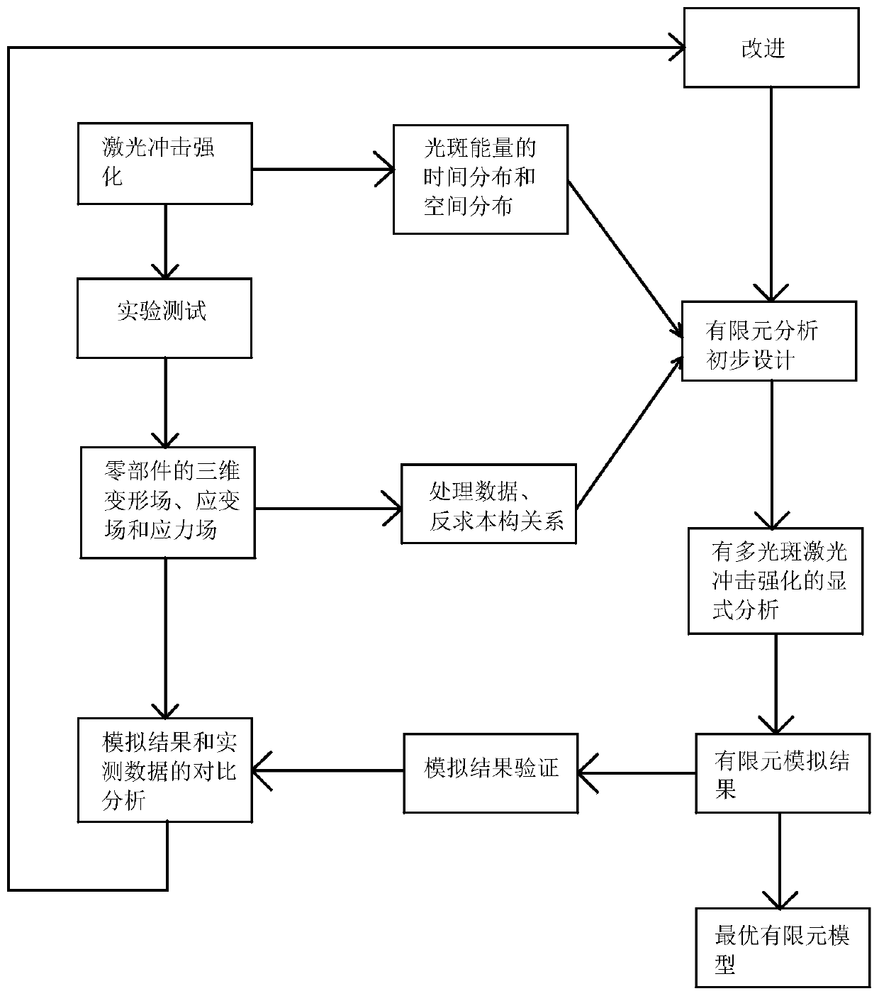
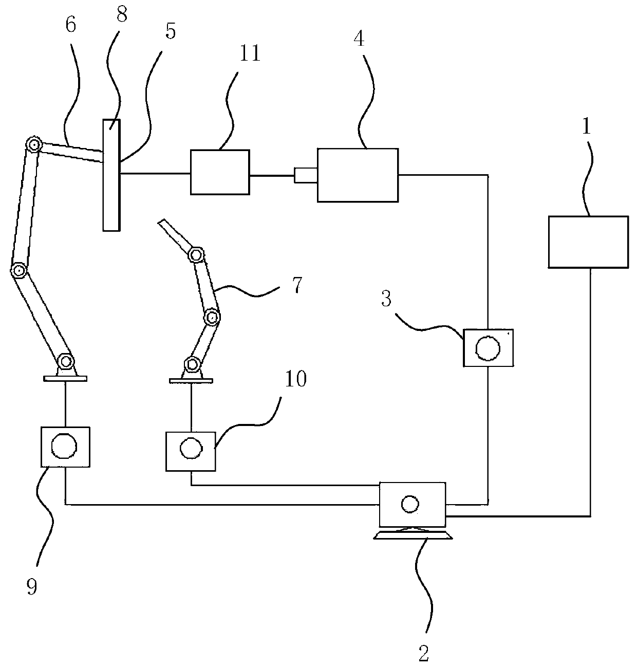
[0023] Such as Figure 1-2 Shown in, a kind of simulation method based on the laser shock data of collection, in one of them embodiment, take the parts and components of the aeroengine impeller that TC4 titanium alloy is made as experimental object, carry out finite element simulation, comprise the following steps:

[0024] a. Use the laser shock strengthening system to process the complex thin-walled blades of the parts, and set the basic processing parameters: the laser energy is 6J, the circular spot size is 6mm, the pulse width is 10ns, the pulse frequency is 5Hz, and the overlap rate 50%;

[0025] b. Using the automatic data collection function of the laser shock peening system, the recorded data includes: the pulse energy of each spot, the pulse width of each spot, the complete time distribution of the selected spot, and the complete spatial distribution of the selected spot. Import the collected spot parameters into MATLAB, fit the spot parameters, obtain the time and ...


PUM


Abstract

The invention relates to a simulation method based on collected laser shock data and a strengthening quality control device. The method comprises the following steps: using a laser shock strengtheningsystem to strengthen a part; collecting light spot parameters generated in the strengthening process; detecting a three-dimensional deformation field, a strain field and a stress field of the part soas to obtain measured data, and reversely solving a constitutive relation of the part in a high strain rate state; generating preliminary design of laser shock peening of the part according to the light spot parameters and the constitutive relation; performing finite element explicit analysis of multi-spot laser shock peening on the preliminary design to obtain a numerical simulation result; comparing and analyzing the simulation result and the measured data, and if the calculated error value is beyond the allowable range, improving the initial design of the finite element analysis until theerror value is within the allowable range to obtain the optimal finite element model. According to the method, a result obtained through finite element simulation analysis has very high credibility, and the control device can well meet the requirement of quality control.

Description

technical field [0001] The invention relates to the field of laser shock strengthening of components, in particular to a simulation method based on collected laser shock data and a strengthening quality control device. Background technique [0002] Laser shock strengthening technology uses high-temperature and high-pressure plasma induced by nanosecond pulsed laser to introduce residual compressive stress with a certain depth into the metal material, which can prevent the expansion of cracks, thereby improving the fatigue resistance of metal parts and further improving their performance. At the same time, the hardness, corrosion resistance, friction and other properties of the material surface are also improved. Laser shock strengthening technology is widely used in aviation, aerospace and other fields. However, the laser shock process is affected by a variety of variable factors, and considering the value of the complex parts themselves, it will inevitably take a lot of tim...

Claims


Application Information

Patent Timeline
Patent Type & Authority Applications(China)
IPC IPC(8): G06F17/50
CPCG06F30/23
Inventor 朱然张永康李毓洲
Owner GUANGDONG LASER PEENING TECH CO LTD
Why Eureka
Try Eureka