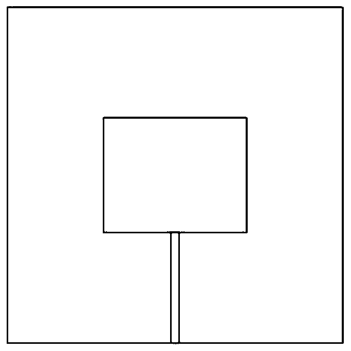
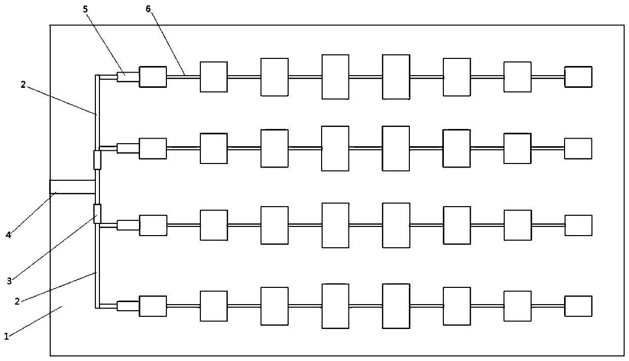
Ka-band standing wave type series-fed microstrip line array antenna, a Ka-band standing wave type series-fed microstrip area array antenna and manufacturing methods thereof

A technology of microstrip line and array antenna, which is applied in the direction of antenna, antenna array, antenna grounding device, etc., which can solve the problems of low space utilization, complicated matching of patch unit current amplitude, large feeder loss, etc., and reduce transmission line loss, compact array element, and small feeder loss

Inactive Publication Date: 2019-08-23
CHANGAN UNIV
View PDF4 Cites 8 Cited by
  • Summary
  • Abstract
  • Description
  • Claims
  • Application Information

AI Technical Summary

Problems solved by technology

[0005] The purpose of the present invention is to overcome the shortcoming of above-mentioned prior art, provide a kind of Ka-band standing wave type series-fed microstrip line array antenna, area array antenna and manufacturing method, solve the feeder line loss of existing microstrip antenna is big, stick to Complicated production of chip unit current amplitude matching and low space utilization

Method used


Image

  • Ka-band standing wave type series-fed microstrip line array antenna, a Ka-band standing wave type series-fed microstrip area array antenna and manufacturing methods thereof
  • Ka-band standing wave type series-fed microstrip line array antenna, a Ka-band standing wave type series-fed microstrip area array antenna and manufacturing methods thereof
  • Ka-band standing wave type series-fed microstrip line array antenna, a Ka-band standing wave type series-fed microstrip area array antenna and manufacturing methods thereof

Examples


Embodiment Construction

[0049] In order to enable those skilled in the art to better understand the solutions of the present invention, the following will clearly and completely describe the technical solutions in the embodiments of the present invention in conjunction with the drawings in the embodiments of the present invention. Obviously, the described embodiments are only It is an embodiment of a part of the present invention, but not all embodiments. Based on the embodiments of the present invention, all other embodiments obtained by persons of ordinary skill in the art without making creative efforts shall fall within the protection scope of the present invention.

[0050] It should be noted that the terms "first" and "second" in the description and claims of the present invention and the above drawings are used to distinguish similar objects, but not necessarily used to describe a specific sequence or sequence. It is to be understood that the data so used are interchangeable under appropriate ...


PUM


Abstract

The invention discloses a Ka-band standing wave type series-fed microstrip line array antenna, a Ka-band standing wave type series-fed microstrip area array antenna and manufacturing methods thereof.The microstrip line array antenna comprises a dielectric substrate, a ground layer, a main feed line, a feed line and a series-fed microstrip line array. The main feed line and the series-fed microstrip line array are both connected to the upper surface of the dielectric substrate. The ground layer is connected to the lower surface of the dielectric substrate. The series-fed microstrip line arraycomprises a first impedance transform matcher and a plurality of array elements. The microstrip area array antenna includes a dielectric substrate, a ground layer, a main feed line, a plurality of second impedance transform matchers, and a plurality of series-fed microstrip line arrays. The main feed line, the plurality of second impedance transform matchers and the plurality of series-fed microstrip line arrays are all connected to the upper surface of the dielectric substrate. The ground layer is connected to the lower surface of the dielectric substrate. One end of the series-fed microstripline array is open-circuited, and the other end of the series-fed microstrip line array is connected to the main feed line through the second impedance transform matchers. The incident wave and the reflected wave are superimposed on the main feed line to realize standing wave transmission. The antenna structure is simplified by using the compact structure and simple design of the series-fed network.

Description

technical field [0001] The invention belongs to the field of antennas, and relates to a Ka-band standing wave series-fed microstrip linear array antenna, an area array antenna and a manufacturing method. Background technique [0002] Compared with other types of antennas, microstrip antennas have a series of advantages such as small size, free structure, low profile, easy integration and low cost, and are widely used. And with the in-depth research and application development of wireless communication, especially in the 5G era that has come, the spectrum resources of low-end frequencies are crowded. Even if the technology of expanding the channel spectrum capacity is adopted, it cannot meet the application needs of wireless communication in the future. In order to obtain a high-speed, high-efficiency, and wide-band wireless communication system, new spectrum resources must be extended to high-end frequencies. Therefore, the millimeter-wave frequency band has become a hot spo...

Claims


Application Information

Patent Timeline
Patent Type & Authority Applications(China)
IPC IPC(8): H01Q1/38H01Q1/48H01Q1/50H01Q21/00H01Q21/08
CPCH01Q1/38H01Q1/48H01Q1/50H01Q21/0006H01Q21/0087H01Q21/08
Inventor 靳钊蔺琛智乔丽萍王晓丽郭晨李楠
Owner CHANGAN UNIV
Why Eureka
Try Eureka