High speed deep tissue imaging system using multiplexed scanned temporal focusing

An imaging system, spatial multiplexing technology, applied in the field of high-speed deep tissue imaging system using multiplexed scanning time focusing, can solve problems such as difficult to apply to awake animals, easy to scatter, and limitations imposed on the overall scanning speed

Inactive Publication Date: 2019-08-23
UNIVERSITY OF VIENNA +1
View PDF6 Cites 4 Cited by
  • Summary
  • Abstract
  • Description
  • Claims
  • Application Information

AI Technical Summary

Problems solved by technology

Even with increased machine scan speeds in the future, fluorescence saturation may eventually impose a limit on overall scan speed, as such increases in scan speed must be accompanied by increased illumination intensities in order to maintain useful signal-to-noise levels
Although other three-dimensional (3D) imaging methods exist that do not rely on point-like two-photon laser scanning, most of them either fail to

Method used


Image

  • High speed deep tissue imaging system using multiplexed scanned temporal focusing
  • High speed deep tissue imaging system using multiplexed scanned temporal focusing
  • High speed deep tissue imaging system using multiplexed scanned temporal focusing

Examples


Embodiment Construction

[0035] Two techniques for Multiplexed Scan Time Focusing (MuST) are disclosed herein. These two techniques include two-photon scanning microscopy and three-photon scanning microscopy. Both MuST techniques (two-photon and three-photon) disclosed provide superior performance for volumetric calcium imaging at high frame rates compared to known techniques.

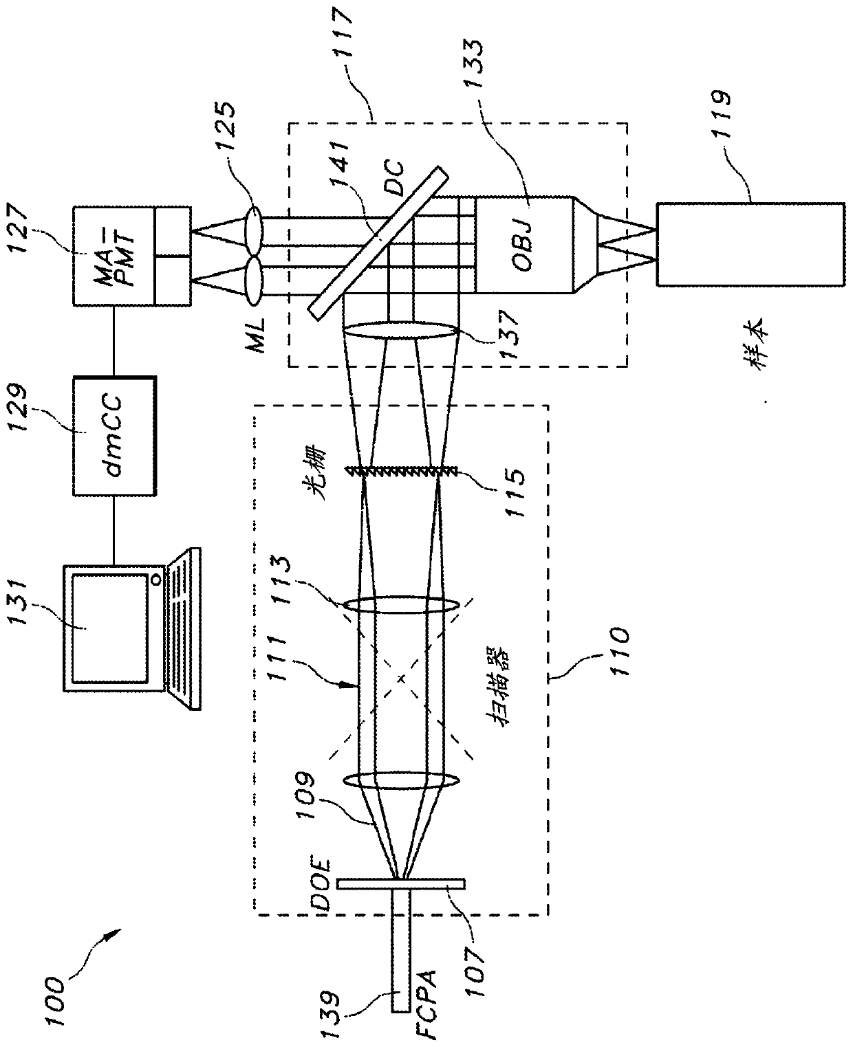
[0036] figure 1 A schematic diagram of an exemplary imaging system 100 is shown. Imaging system 100 includes a pulsed output laser module 139 that outputs (or emits) a pulsed primary laser beam 109 comprising repeating ultrashort light pulses (which may be referred to as "laser pulses"). For example, laser module 139 may be implemented using, for example, a commercial or custom fiber-based chirped pulse amplifier (FCPA). The laser module 139 may output light pulses at a repetition rate of, for example, 1 megahertz (MHz) to 5 MHz. The duration of each light pulse can be, for example, less than 100 picoseconds (picosecond, ...


PUM


Abstract

A tissue imaging system includes a laser module for outputting a laser pulse, an optical delay module configured to split a laser pulse received from the laser module into a plurality of time-delayedsub-pulses, a telescope for delivering the sub-pulses from the optical delay module to a target volume and a photodetector configured to collect photons generated within the target volume in responseto excitation of the target volume by the first and second sub-pulses. The system may further include a spatial multiplexing module configured to receive the temporally multiplexed laser pulse from the optical delay module and splitting the temporally multiplexed laser pulse into a plurality of sub-beams including a first sub-beam and a second sub-beam, wherein the first sub-beam and the second sub-beam are spatially separated with respect to a first image plane formed at a first depth within the target volume and with respect to a second image plane formed at a second depth within the targetvolume.

Description

[0001] Cross References to Related Applications [0002] This application claims priority to US Provisional Application No. 62 / 414,788, filed October 30, 2016, the specification of which application is hereby incorporated in its entirety for all purposes. Background technique [0003] A major goal of modern neuroscience is to understand how neural networks perform cognition-related functions. To achieve this goal, it is useful to simultaneously and independently record the activity of large neurons, the building blocks of even the simplest neural networks. However, this task has been hampered by shortcomings in available tools and techniques. [0004] A light microscope solves this problem by nearly simultaneously recording the activity of thousands of neurons in the rodent brain, thereby improving the understanding of information processing in the mammalian brain (including in various healthy and pathological states of the human brain). A major leap forward in the fundamen...

Claims


Application Information

Patent Timeline
IPC IPC(8): G01N21/63G01N21/64H01S3/067
CPCG01N21/6408G02B21/0076G01N21/6458G02B21/367G01N2201/105H01S3/005G01N21/6486
Inventor 阿里帕莎·瓦兹里
Owner UNIVERSITY OF VIENNA
Why Eureka
Try Eureka