

Microcatheter with head end capable of being eluted
A micro-catheter, catheter technology, applied in the direction of catheter, coating, etc., to achieve excellent biological safety, reduce psychological pressure, reduce the effect of surgical steps
- Summary
- Abstract
- Description
- Claims
- Application Information
AI Technical Summary
Problems solved by technology
Method used
Image

Examples
Embodiment 1
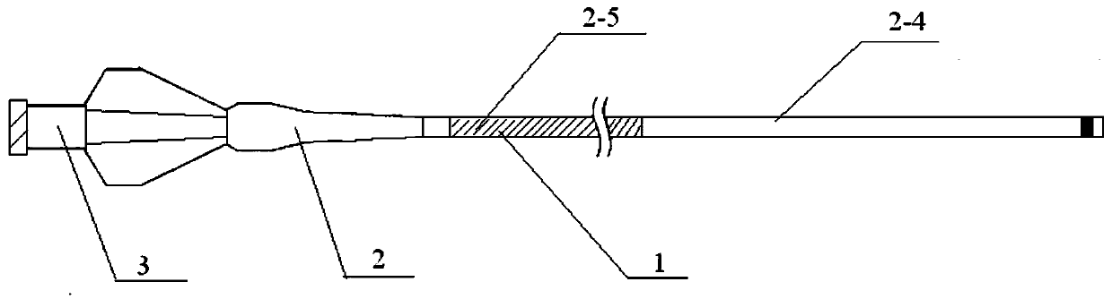
[0033] Such as Figure 1-2 As shown, the head-end elutable microcatheter includes a microcatheter main body 1, a stress expansion tube 2 and a Luer connector 3; the microcatheter main body 1 is connected to one end of the stress expansion tube 2, and the other end of the stress expansion tube 2 is connected to The Luer connector 3 is connected; the surface of the microcatheter main body 1 is coated with a release coating.
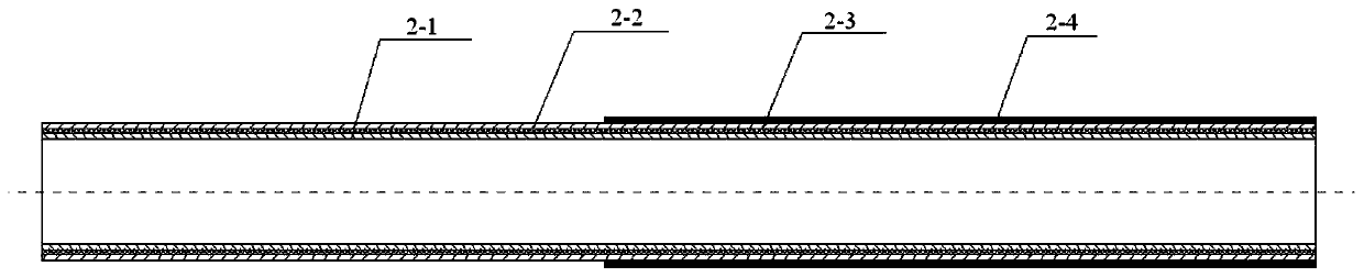
[0034] The cross-sectional structure of the microcatheter main body 1 includes an inner layer 2-1, an intermediate layer 2-2 and an outer layer 2-3 from the inside to the outside; the material of the inner layer 2-1 is a PTFE catheter, and the middle layer 2-2 It is a metal lining wire layer of braided or coiled spring structure, and the material of the outer layer 2-3 is PEBAX catheter.
[0035] The PEBAX catheter in the outer layer 2-3 is welded by several sections of PEBAX materials with different hardness; wherein the distal end material is softer than...
Embodiment 2
[0038] 10g PVA (Airvol 523 U.S. air chemistry) heating is dissolved in 125g deionized water, then adds 5g Tween 80 and dissolves. Then add 1 g of 10% glutaraldehyde solution and the resulting solution can be directly used for coating after cooling. The coating adopts the pulling and dipping process. The distal end of the elutable microcatheter described in Example 1 is dipped 10 cm below the liquid surface. After dipping for 10 seconds, it is then lifted upwards at a speed of 10 mm / s. The distal end is completely clear of the liquid surface. Finally, after waiting for 30 seconds, transfer the microcatheter to an oven after the surface of the microcatheter is dry, and bake at 60 degrees for 2 hours.
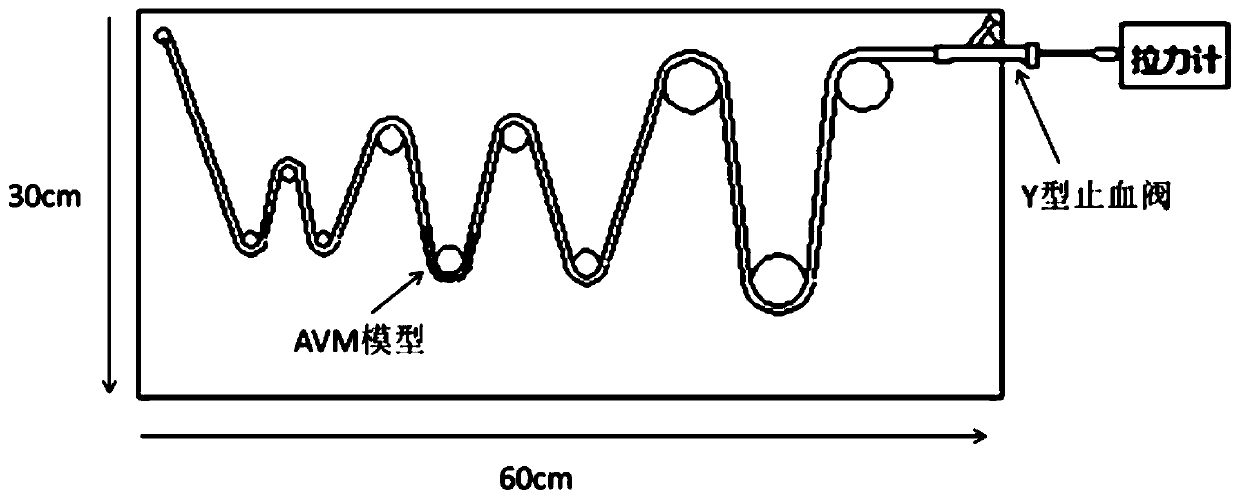
[0039] With Onyx glue reflux embedding test, the withdrawal force is: 30±10gF (embedding length: 3cm).
[0040] The test method of withdrawal force is as follows:
[0041] (1) Soak the microcatheter in 37°C normal saline for 10 minutes;
[0042] (2) if image 3 Set the test l...
Embodiment 3
[0055] 10g PVP (K30 U.S. BASF) was heated and dissolved in 125g deionized water, and then 10g Proxamer 188 was added for dissolution. The resulting solution can be used directly for coating after cooling.
[0056] The coating adopts the pulling and dipping process. The distal end of the elutable microcatheter described in Example 1 is dipped 10 cm below the liquid surface. After dipping for 10 seconds, it is then lifted upwards at a speed of 20 mm / s. The distal end is completely clear of the liquid surface. Finally, after waiting for 30 seconds, transfer the microcatheter to an oven after the surface of the microcatheter is dry, and bake at 60 degrees for 2 hours.
[0057] According to the test method described in Example 1, with Onyx glue reflux embedding test, the withdrawal force is: 20 ± 10gF (embedding length 3cm).
PUM
| Property | Measurement | Unit |
|---|---|---|
| Length | aaaaa | aaaaa |
| Length | aaaaa | aaaaa |
| Thickness | aaaaa | aaaaa |
Abstract
Description
Claims
Application Information