

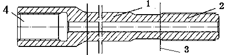
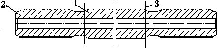
Manufacturing method for impact threaded brazing rod
A manufacturing method and thread technology, applied in the field of drilling rod manufacturing, can solve the problems of waste, inability to change, lack of flexibility, etc., and achieve the effects of reducing production costs, reducing production time, and saving production time
- Summary
- Abstract
- Description
- Claims
- Application Information
AI Technical Summary
Problems solved by technology
Method used
Image

Examples
Embodiment 1
[0073] Embodiment 1: T45-3660 ordinary drill rod,
[0074] Threaded male joint material: 23CrNi3Mo (EN40B), length 200mm.
[0075] Heat treatment method 1: Carburizing at 930°C, then air cooling, the thickness of the carburized layer is 0.8-1.0mm.
[0076] Middle rod material: 22SiMnCr2NiMo (FF710), length 3280mm.
[0077] Heat treatment method 1: carburizing at 930°C, then air cooling, the thickness of the carburized layer is 0.6-0.8mm.
[0078] a: Use friction welding to weld the processed rod body and male joint;
[0079] b: 840°C annealing treatment at the welding place to remove internal and external welding flashes, that is, welding nodules;
[0080] c: 930 ° C quenching treatment at the welding place again, and then air cooling;
[0081] d: Non-destructive testing of welds;
[0082] e: Straightening and tempering at 240°C to remove straightening stress;
[0083] f: On the lathe, both ends are corrected, the parallelism is less than 0.4mm, and the perpendicularity ...
Embodiment 2
[0085] Embodiment 2: T38-R32-3700 common drill rod,
[0086] Male connector material: 22SiMnCr2NiMo (FF710), T38 male connector length 160mm, R32 male connector length 140mm, heat treatment method 1: 930°C carburizing, then air cooling, carburized layer thickness 0.6-0.8mm.
[0087] Middle hexagonal rod material: 55SiMnMo, length 3420mm.
[0088] Heat treatment method: medium frequency continuous heating, 880°C oil quenching.
[0089] a: Use friction welding to weld the processed rod body and male joint;
[0090] f: 800°C annealing treatment at the welding place to remove internal and external welding flashes, that is, welding nodules;
[0091] g: The welding place is quenched again at 860°C, and then air-cooled;
[0092] h: non-destructive testing of welds;
[0093] i: Straightening and tempering at 240°C to remove straightening stress;
[0094] f: On the lathe, both ends are corrected, the parallelism is less than 0.4mm, and the perpendicularity to the central axis is l...
PUM
| Property | Measurement | Unit |
|---|---|---|
| Length | aaaaa | aaaaa |
Abstract
Description
Claims
Application Information