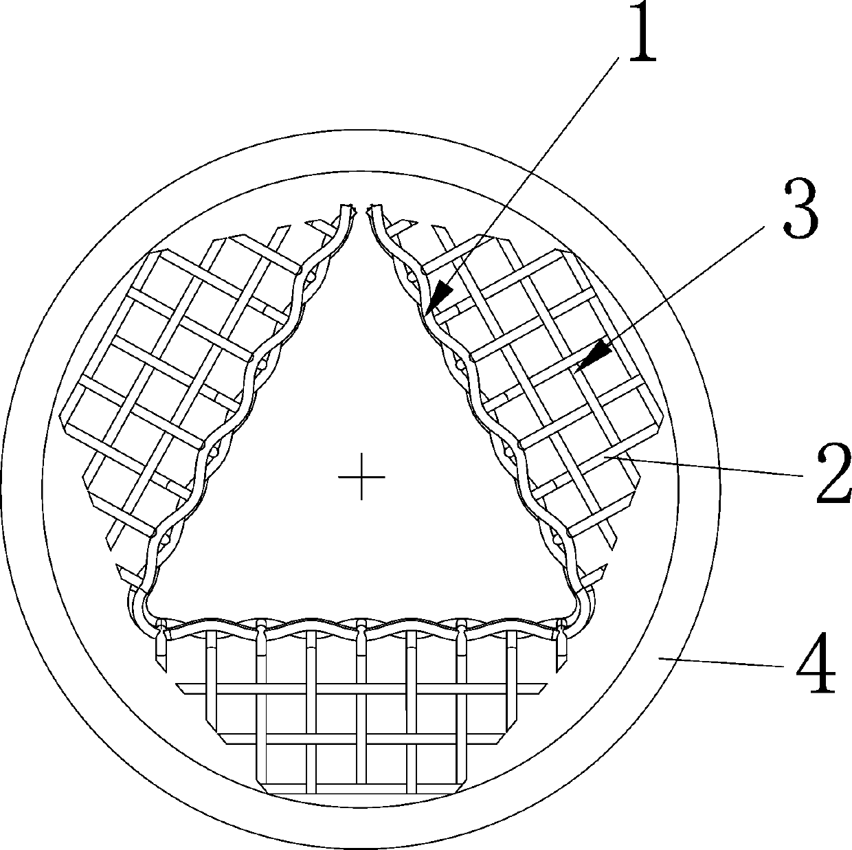
Nitrogen oxide catalytic reaction net

A catalytic reaction and nitrogen oxide technology, applied in the field of reaction nets, can solve the problems of catalytic reaction nets that cannot withstand high temperatures, low reaction efficiency, and long distances, and achieve high resistance to peeling, effective reactions, and good high temperature resistance. Effects of Corrosion and Oxidation Resistance

Pending Publication Date: 2019-08-30
YUYAO DIANBO MACHINERY
View PDF0 Cites 0 Cited by
  • Summary
  • Abstract
  • Description
  • Claims
  • Application Information

AI Technical Summary

Problems solved by technology

[0003] At present, companies have different treatment methods for nitrogen oxides. At present, there are catalytic reaction nets to deal with nitrogen oxides, but because this catalytic reaction net cannot withstand high temperatures above 1200°C, at the same time, due to the catalytic The limitation of the structure of the reaction network leads to the distance between it and the flame. The above two disadvantages are not conducive to the progress of the reaction, resulting in low reaction efficiency.

Method used


Image

  • Nitrogen oxide catalytic reaction net

Examples


Embodiment 2

[0025] Embodiment 2: Compared with Embodiment 1, the difference lies in the shape of the flanging, and the rest are the same.

[0026] The shape of the flanging can also directly adopt a trapezoidal shape, which reduces the process and can also effectively contact the flame, which is beneficial to the reaction.

Embodiment 3

[0027] Embodiment 3: Compared with Embodiment 1, the difference is that the mass fraction of silk thread is different, and the rest are the same.

[0028] The silk thread includes the following components in parts by mass: 0.031 parts of carbon, 0.4 parts of silicon, 0.12 parts of manganese, 0.0043 parts of sulfur, 58.1 parts of nickel, 23.1 parts of chromium, 0.28 parts of titanium, 1.61 parts of aluminum, 0.023 parts of calcium, boron 0.0005 parts and iron 16.3312 parts. One of the advantages of using this formula is that it can withstand high temperatures above 1200°C.

[0029] According to the experiment, compared with the original structure, the emission of the reaction net of the present invention is reduced from 34 joules to 15 joules.

Embodiment 4

[0030] Embodiment 4: Compared with Embodiment 1, the difference is that the mass fraction of the thread, the side length of the through hole, the diameter of the thread, and the density of the thread are different, and the rest are the same.

[0031] The side length of the through holes formed by interweaving silk threads in the reaction net is 2.51 mm, the diameter of the silk threads is 0.8 mm, and the shape of the through holes is square. In this way, the rate of reaction can be achieved the fastest.

[0032] The thread has a density of 8.21 g / cm³.

[0033] The silk thread includes the following components in parts by mass: 0.032 parts of carbon, 0.41 parts of silicon, 0.19 parts of manganese, 0.0038 parts of sulfur, 57.7 parts of nickel, 22.9 parts of chromium, 0.27 parts of titanium, 1.35 parts of aluminum, 0.018 parts of calcium, boron 0.0004 parts and iron 17.3258 parts. One of the advantages of using this formula is that it can withstand high temperatures above 1200°...


PUM

PropertyMeasurementUnit
Diameteraaaaaaaaaa
Densityaaaaaaaaaa
Densityaaaaaaaaaa

Abstract

The invention discloses a nitrogen oxide catalytic reaction net, which comprises a reaction net body, wherein the reaction net body is formed by interweaving a plurality of wires, the top portion andthe bottom portion of the reaction net body are respectively provided with a plurality of outward flanges, the outer edges of the flanges contact the inner wall of a reaction pipe, and the wire comprises the following components by mass: 0.02-0.04 part of carbon, 0.3-0.5 part of silicon, 0.1-0.2 part of manganese, 0.0035-0.006 part of sulfur, 56.3-59.2 parts of nickel, 21.2-23.5 parts of chromium,0.15-0.3 part of titanium, 1.23-1.66 parts of aluminum, 0.014-0.031 part of calcium, 0.0003-0.0008 part of boron, and 16.223-16.665 parts of iron. According to the present invention, by improving thestructure and the components of the reaction net, the nitrogen oxide catalytic reaction net has functions of high-temperature resistance, rapid reaction and effectiveness.

Description

technical field [0001] The invention relates to the technical field of reaction nets, in particular to a nitrogen oxide catalytic reaction net. Background technique [0002] Nitrogen oxides, which include compounds such as nitrous oxide (N2O), nitrogen monoxide (NO), nitrogen dioxide (NO2), dinitrogen trioxide (N2O3), dinitrogen tetroxide (N2O4), and dinitrogen pentoxide Nitrogen (N2O5), etc. Except for nitrogen dioxide, other nitrogen oxides are extremely unstable, and turn into nitrogen dioxide and nitric oxide when exposed to light, humidity or heat, and nitrogen monoxide turns into nitrogen dioxide. Exposure in occupational environments is therefore a mixture of several gases commonly referred to as gunpowder (gas), mainly nitric oxide and nitrogen dioxide, with nitrogen dioxide predominating. Nitrogen oxides are toxic to varying degrees. [0003] At present, companies have different treatment methods for nitrogen oxides. At present, there are catalytic reaction nets ...

Claims


Application Information

Patent Timeline
IPC IPC(8): B01D53/86B01D53/56
CPCB01D53/8631
Inventor 史渭森
Owner YUYAO DIANBO MACHINERY
Why Eureka
Try Eureka