
A medium and low temperature waste heat driven flash-injection-absorption combined cooling, heating and power system

A technology of combined cooling, heating and power, low-temperature waste heat, applied in refrigerators, steam engine installations, refrigeration and liquefaction, etc., can solve the problems of complex generator structure, high power consumption of solution pump, low steam intake of turbine, etc. Achieve maximum utilization of energy, save heat transfer area, and increase cycle efficiency.

Active Publication Date: 2021-07-09
KUNMING UNIV OF SCI & TECH
View PDF0 Cites 0 Cited by
  • Summary
  • Abstract
  • Description
  • Claims
  • Application Information

AI Technical Summary

Problems solved by technology

[0003] However, after analyzing the absorption power cycle currently proposed in the world, it is found that the cycle rate of the absorption power cycle is generally high, and the steam production of the generator is small, resulting in a large power consumption of the solution pump and a large amount of steam intake of the turbine. Less output work; when the difference between the generator pressure and the absorption pressure is large, a large throttling pressure drop will be generated during the flow of a large amount of dilute solution as the absorbent from the high-pressure generator to the low-pressure absorber ( Exergy) loss, the structure of the generator is also more complicated

Method used


Image

  • A medium and low temperature waste heat driven flash-injection-absorption combined cooling, heating and power system
  • A medium and low temperature waste heat driven flash-injection-absorption combined cooling, heating and power system
  • A medium and low temperature waste heat driven flash-injection-absorption combined cooling, heating and power system

Examples


Embodiment 1

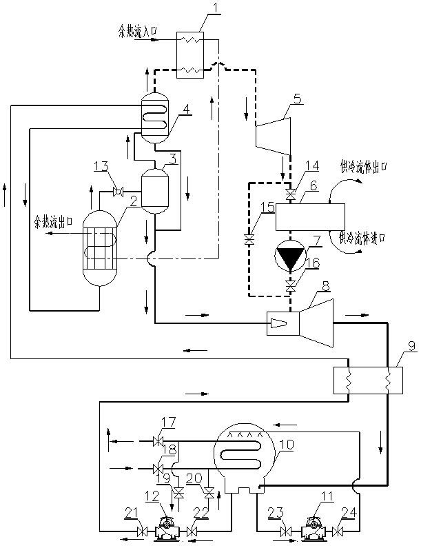
[0030] like figure 1 and 3 As shown, the medium and low temperature waste heat-driven flash evaporation-injection-absorption combined cooling, heating and power system includes superheater 1, waste heat heater 2, flash evaporator 3, rectifier 4, expander 5, cooling and heat exchange 6, booster compressor 7, jet ejector 8, regenerator 9, absorber 10, absorption pump 11, solution pump 12, throttle valve 13 and stop valve, the concentration of circulating working medium in the absorber 10 is relatively high The high working fluid is pumped into the regenerator 9 and the rectifier 4 through the solution pump 12 to the outlet of the solution to be preheated, and then flows into the waste heat heater 2, and the waste heat flows into the waste heat heater after being overheated by the superheater 1 The waste heat inlet of 2 heats the working fluid with a high concentration of circulating working fluid to heat the solution, and the high-temperature working fluid on the top of the was...

Embodiment 2

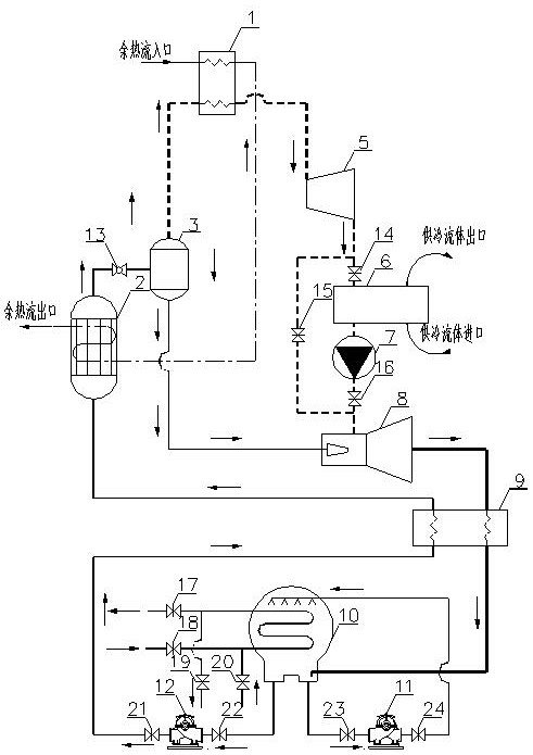
[0034] like figure 2 and 3 As shown, the medium and low temperature waste heat-driven flash evaporation-injection-absorption combined cooling, heating and power system includes a superheater 1, a waste heat heater 2, a flash evaporator 3, an expander 5, a cooling heat exchanger 6, a booster Compressor 7, jet ejector 8, regenerator 9, absorber 10, absorption pump 11, solution pump 12, throttle valve 13 and stop valve, absorber 10 contains circulating working medium concentration The solution outlet is pumped into the regenerator 9 by the solution pump 12 to be preheated, and then flows into the waste heat heater 2, and the waste heat flow passes through the superheater 1 and enters the waste heat inlet of the waste heat heater 2 to control the concentration of circulating working fluid. The higher working fluid heats the solution, and the high-temperature working fluid on the top of the waste heat heater 2 is connected to the flash evaporator 3 through the throttling valve 13...


PUM


Abstract

The invention relates to a medium-low temperature waste heat driven flash-injection-absorption combined cooling, heating and power supply system, which belongs to the technical field of new energy and energy saving. The medium and low temperature waste heat-driven flash-injection-absorption combined cooling, heating and power system includes superheater, waste heat heater, flash evaporator, rectifier, expander, cooling heat exchanger, booster compressor, injection Ejectors, regenerators, absorbers, absorption pumps, solution pumps, throttle and shut-off valves. This system can realize combined cooling, heating and power supply or combined heating and power supply according to the needs of users. No matter whether the compound cycle system constructed by the present invention is operated under the combined cooling, heating and power supply or combined heating and power supply mode, only a small part of the external heat loss can be realized. Maximum utilization of energy.

Description

technical field [0001] The invention relates to a medium-low temperature waste heat-driven flash evaporation-injection-absorption combined cooling, heating and power supply system, which belongs to the technical field of new energy and energy saving. Background technique [0002] The organic Rankine cycle system driven by medium and low temperature heat energy has the advantages of simple structure, high reliability, low operation and maintenance costs, can make full use of the temperature difference between the hot and cold ends for efficient operation, can realize unattended automatic operation and high efficiency, and is very suitable for construction Cooling (heating) combined power supply distributed energy system. In recent years, medium and low temperature thermal energy-driven ORC technology and combined cooling / heating power technology based on ORC technology have become international research hotspots. However, most of the ORCs currently studied are condensing ORC...

Claims


Application Information

Patent Timeline
Patent Type & Authority Patents(China)
IPC IPC(8): F01K25/10F25B25/02
CPCF01K25/103F01K25/106F25B25/02
Inventor 王辉涛余伟王建军朱道飞陶帅赵玲玲黄靖伦徐煜
Owner KUNMING UNIV OF SCI & TECH
Learn More