LED driving circuit, load control system, load system and control method

An LED driver and circuit technology, applied in energy-saving control technology, electric light source, electrical components, etc., can solve problems such as reducing system efficiency and increasing system loss

Active Publication Date: 2019-09-03
MAXIC TECHNOLOGY CORPORATION
View PDF6 Cites 6 Cited by
  • Summary
  • Abstract
  • Description
  • Claims
  • Application Information

AI Technical Summary

Problems solved by technology

However, refer to figure 1 As shown, when the existing linear LED driver is used with the thyristor dimmer, in order to maintain the conduction of the TRIAC switch of the thyristor dimmer, there must be a bleeding current (BleederCurrent), refer to figure 2 As shown, when the maximum conduction angle of the TRIAC switch is used...

Method used


Image

  • LED driving circuit, load control system, load system and control method
  • LED driving circuit, load control system, load system and control method
  • LED driving circuit, load control system, load system and control method

Examples


Embodiment 1

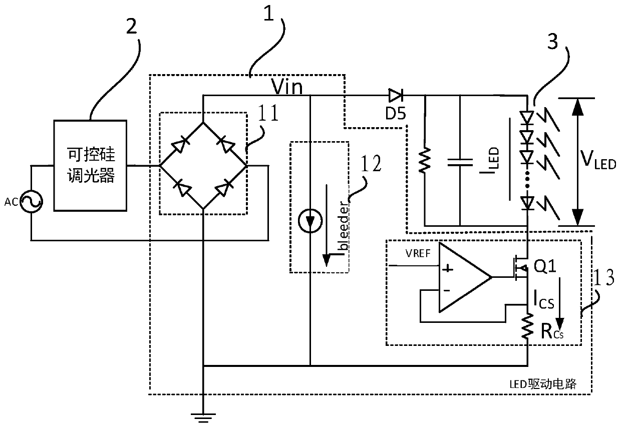
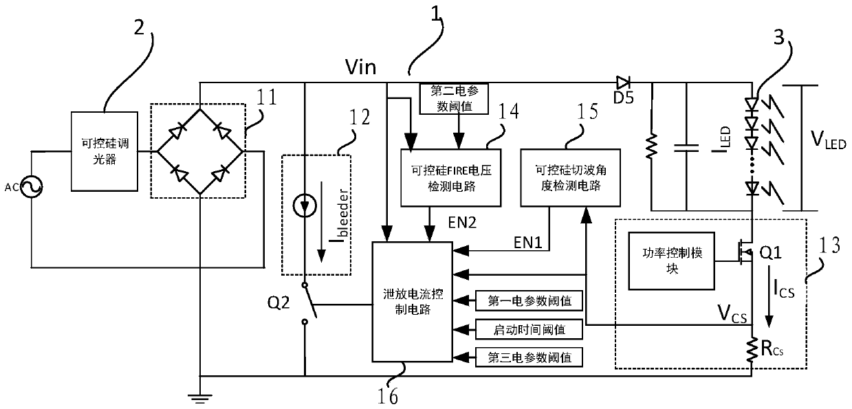
[0060] The present invention provides a LED driving circuit, referring to image 3As shown, the LED drive circuit 1 includes: rectifier circuit 11, discharge circuit 12, LED constant current control circuit 13, SCR FIRE voltage detection circuit 14, SCR wave cutting angle detection circuit 15 and discharge current control circuit 16;

[0061] The discharge circuit 12, the LED constant current control circuit 13 and the thyristor FIRE voltage detection circuit 14 are respectively connected to the rectifier circuit 11; the thyristor wave cutting angle detection circuit 15 is connected to the LED constant current control circuit 13; the discharge current control circuit 16 are respectively connected with the thyristor cutting wave angle detection circuit 15 and the thyristor FIRE voltage detection circuit 14;

[0062] The SCR wave cutting angle detection circuit 15 detects the first electrical parameter signal value representing the SCR wave cutting angle, compares it with the p...

Embodiment 2

[0127] Such as Figure 14 As shown, based on the same inventive concept, the embodiment of the present invention also provides an LED load control system, including: a thyristor dimmer 2, and at least one of the above-mentioned embodiment 1 connected in parallel with the thyristor dimmer 2 The LED driver circuit 1 described in .

[0128] Regarding the LED load control system in the above-mentioned embodiment, the specific way of performing operations of the thyristor dimmer and the LED driving circuit has been described in detail in the LED driving circuit of the first embodiment above, and will not be described in detail here Explain.

Embodiment 3

[0130] Such as Figure 14 As shown, based on the same inventive concept, the embodiment of the present invention also provides an LED load system, including: a thyristor dimmer 2, and at least one of the above-mentioned embodiment ones connected in parallel with the thyristor dimmer 1 The above LED driving circuit 1 and the LED load 3 connected to the LED driving circuit 1 .

[0131] Regarding the LED load system in the above-mentioned embodiment, the specific way of performing operations of the thyristor dimmer and the LED driving circuit has been described in detail in the LED driving circuit of the above-mentioned embodiment 1, and will not be elaborated here illustrate.


PUM


Abstract

The invention discloses an LED driving circuit which is connected with a thyristor dimmer and which comprises a rectifying circuit, a bleeder circuit connected with the rectifying circuit, an LED constant-current control circuit, a thyristor turn-on FIRE voltage detecting circuit, a thyristor cut wave angle detecting circuit and a bleeder current control circuit. The thyristor cut wave angle detecting circuit generates a first result signal. The thyristor turn-on FIRE voltage detecting circuit generates a second result signal. The bleeder current control circuit, when receiving the first result signal and the second result signal, instructs the bleeder circuit to start a high-efficiency mode in which the bleeder circuit is started by delaying the start time of following preset N half-wavecycles of a DC bus voltage signal Vin with a preset time Tdelay, wherein N is a positive integer. The LED driving circuit can reduce its own loss, improve the driving efficiency of the thyristor, reduce the cost, and saves power in the high-efficiency mode.

Description

technical field [0001] The invention relates to the field of LED drive, in particular to an LED drive circuit, an LED load control system, an LED load system and a control method for the LED drive circuit. Background technique [0002] In recent years, high-brightness LED (Light-emitting diode) lighting is gradually replacing traditional light sources such as incandescent lamps and fluorescent lamps with the advantages of high luminous efficiency, long life, high reliability and no pollution. In some applications, it is hoped that the brightness of the light can be adjusted in some cases in order to further save energy and provide comfortable lighting. Usually, a thyristor dimmer is used for dimming, and the thyristor dimmer is connected through a connected LED driver The Triode for Alternating Current Semiconductor Switch (TRIAC) realizes dimming. Although the LED driver adopts the linear driving method, it has the advantages of simple structure, low Electromagnetic Interf...

Claims


Application Information

Patent Timeline
IPC IPC(8): H05B33/08H05B44/00
CPCH05B45/37H05B45/00Y02B20/40
Inventor 牟在鑫张攀
Owner MAXIC TECHNOLOGY CORPORATION
Why Eureka
Try Eureka