
Steel weight-reduction type double-web pressing slide wheel and manufacturing method thereof

A technology of webs and pulleys, applied in the direction of belts/chains/gears, portable lifting devices, components with teeth, etc., can solve the problems of poor precision of rolling pulley rims, deterioration of mechanical properties of steel parts, high pulley scrap rate, etc. , to achieve the effect of long wear-resistant service life, reasonable structural design, good strength and rigidity of the wheel groove

Pending Publication Date: 2019-09-10
SHANGHAI ZHENHUA PORT MACHINARY HEAVY IND CO LTD
View PDF0 Cites 0 Cited by
  • Summary
  • Abstract
  • Description
  • Claims
  • Application Information

AI Technical Summary

Problems solved by technology

From a technical point of view, the pulley has made significant progress in the past 30 years, but it has always been inseparable from the production method mainly based on thermal processing (casting, forging, hot rolling). Traditional casting and forging pulleys have large dead weight and large moment of inertia. Shortcomings such as long cycle and high cost are increasingly unable to keep up with the needs of users, and the production cost is high, and the product price is expensive. Many users are unwilling to adopt
Hot-rolled pulley rope groove precision is poor, product consistency is not good, many users are unwilling to use
The existing conventional pulleys on the market are mainly casting pulleys or rolling pulleys. The casting pulleys are cast in solid molds, sand molds and investment castings, but the structure is poor in density, and casting defects such as porosity, pores, and sand sticking inevitably exist. The workpiece is repaired, and the casting pulley is heavy, and the corresponding rotation resistance is also large
The web and rim of the rolled pulley are hot-rolled from a single steel plate, and only a single-panel structure can be used. The thickness of the web is restricted by the thickness of the wheel rim and cannot be adjusted freely. The overall thickness of the web is too thick. The accuracy is poor, the thickness of the rope groove in the circumferential direction is uneven, and the pulley jumps and abnormal noise occurs when the pulley rotates at high speed, and deformation occurs in severe cases
Because the rolled pulley is produced by the overall hot rolling method of the rim, the sulfide, oxide, silicate and other non-metallic inclusions inside the rim are pressed into thin sheets, resulting in layering of the pulley material, and layering makes the steel parts The mechanical properties are greatly deteriorated, and in severe cases, interlayer tearing will occur, which has a great impact on the quality of the pulley, so the precision of the rolled pulley rim is poor and the service life is short
In addition, the surface oxidation is more serious during rolling, and decarburization will occur on the surface of the pulley. After decarburization, the hardness of the pulley will decrease, and the wear resistance and life will decrease greatly. During the hot rolling process, the surface of the pulley will have iron oxide scales off, which will adversely affect subsequent processing. , so the rolling pulley scrap rate is high
[0004] The existing cast pulley has heavy weight, high cost, poor precision of rolling pulley, poor product consistency, and the rope groove angle cannot be flexibly customized according to user needs
In recent years, domestic manufacturers have developed various pulleys made of polymer plastics, or pasted replaceable plastic sleeves in the rope grooves of steel pulleys, but they can only be used in parts that require light weight and low operating frequency. For heavy-duty cranes (such as container cranes), steel pulleys must be used due to the high quality and reliability of the pulleys.

Method used


Image

  • Steel weight-reduction type double-web pressing slide wheel and manufacturing method thereof
  • Steel weight-reduction type double-web pressing slide wheel and manufacturing method thereof
  • Steel weight-reduction type double-web pressing slide wheel and manufacturing method thereof

Examples


Embodiment Construction

[0036] The technical solutions of the present invention will be further described below in conjunction with the accompanying drawings and embodiments.

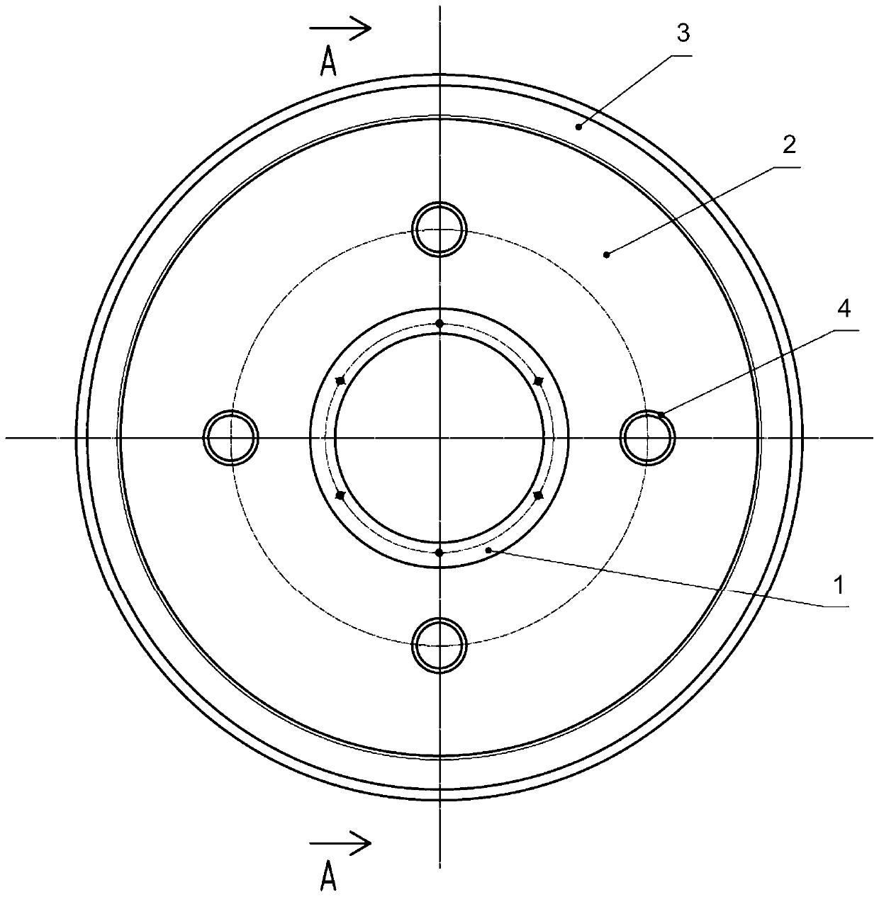
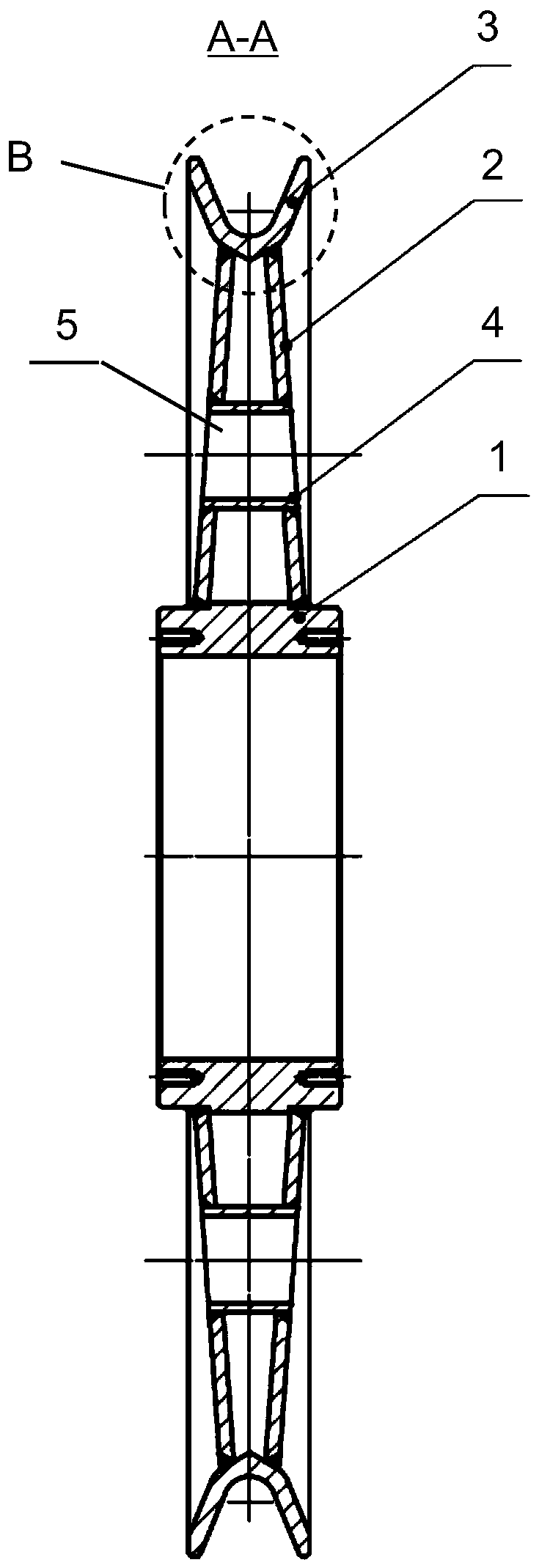
[0037] Please combine Figure 1 to Figure 3 As shown, a kind of steel weight reduction double-panel plate pressing pulley provided by the present invention, said pulley comprises wheel hub 1, the web plate 2 that is connected on the wheel hub 1, and the rim 3 that is connected on the web plate 2, above-mentioned is The prior art part will not be repeated here. The difference from the prior art is:

[0038] Preferably, the hub 1 is configured as a tubular structure.

[0039] Preferably, the web 2 has two pieces, both of which are in the shape of a hollow ring, and are arranged as a figure-eight supporting frame structure welded on the hub 1 . The big mouth end of this figure-eight supporting frame structure is welded on the wheel hub 1.

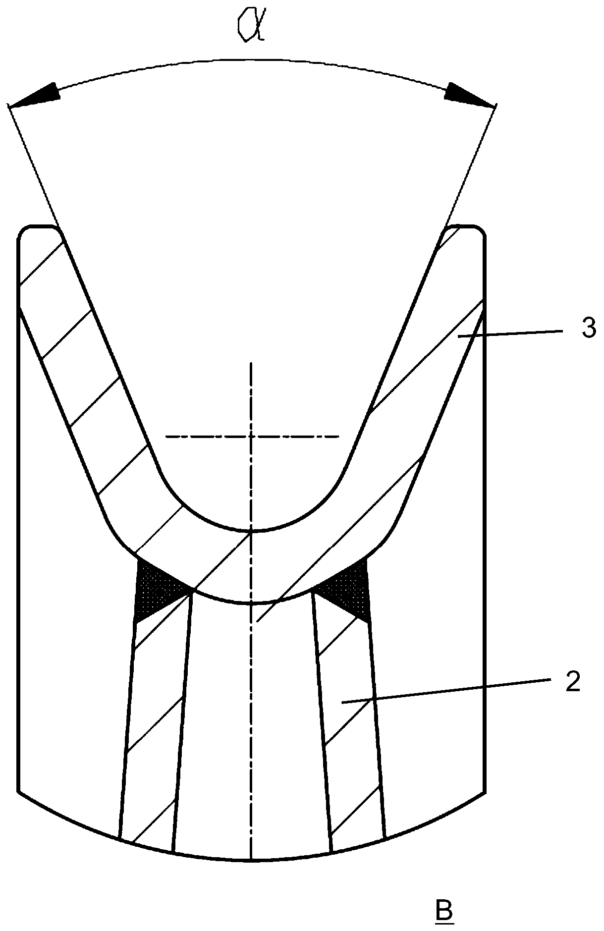
[0040] Preferably, the rim 3 is an annular structure with a U-shaped cross-section, th...


PUM


Abstract

The invention provides a steel weight-reduction type double-web pressing slide wheel and a manufacturing method thereof. The slide wheel comprises a hub, webs connected onto the hub, and rims connected onto the webs, wherein the hub is of a tubular structure; the two webs are in the shapes of hollow circular ring shaped plates, and are arranged to be an inverted-V-shaped supporting framework structure which is connected onto the hub; the rims are of U-shaped section circular ring shaped structures; the outer side surfaces of the rims are connected onto the webs, and rope slots are formed in the inner side surfaces of the rims; the two webs are connected onto the hub, and the rims are connected onto the webs; and a trapezoidal section is formed among the hubs, the two webs and the rims. Thesteel weight-reduction type double-web pressing slide wheel has the characteristics of a reasonable structural design, good strength and rigidity, light dead load, wheel slot wear resistance and a long service life, and can completely replace a conventional rolling slide wheel.

Description

technical field [0001] The invention relates to a pulley, more specifically, to a steel weight-reducing double-width plate pressing pulley and a manufacturing method thereof, and is especially suitable for a steel pulley used in crane machinery and other industries. Background technique [0002] Pulleys are widely used in various lifting and transportation machinery as one of the load-bearing components. The steel wire rope is wound in the pulley rope groove, and the force is transmitted to the steel wire rope through the drive of the drum to realize lifting or reciprocating movement of the mechanism, thereby moving heavy objects. During the force transmission process, the steel wire rope and the inner wall of the pulley groove Mutual extrusion and friction occur. Pulleys must be used in places where steel wire ropes are used, such as lifting and transportation machinery, mining machinery, construction machinery, workshop driving, and deep-sea engineering. Each pulley has ...

Claims


Application Information

Patent Timeline
IPC IPC(8): F16H55/50B23P15/00
CPCF16H55/50B23P15/00
Inventor 陈创业朱国和陈阳杜影杨金昌
Owner SHANGHAI ZHENHUA PORT MACHINARY HEAVY IND CO LTD
Features
  • Generate Ideas
  • Intellectual Property
  • Life Sciences
  • Materials
  • Tech Scout
  • Unparalleled Data Quality
  • Higher Quality Content
  • 60% Fewer Hallucinations
Learn More