
Pipeline shot blasting derusting machine

A derusting machine and pipeline technology, applied in the direction of abrasive jetting machine tools, used abrasive processing devices, abrasives, etc., can solve the problems of difficult to meet the requirements of noise control in environmental protection workshops, unfavorable production state control, and high working noise. Achieve the effect of reducing the difficulty of repair and maintenance, facilitating on-site installation, and meeting environmental protection

Pending Publication Date: 2019-09-13
廊坊市鼎盛机械设备有限公司 +1
View PDF0 Cites 0 Cited by
  • Summary
  • Abstract
  • Description
  • Claims
  • Application Information

AI Technical Summary

Problems solved by technology

[0002] The pipeline shot blasting derusting machine is the equipment used in the derusting process of the steel pipe anti-corrosion layer coating operation. The traditional pipeline shot blasting derusting machine adopts the method of directly falling the pellets after derusting into the bucket elevator, which requires shot blasting. There is a certain drop between the room and the bucket elevator. In order to ensure the height of the drop, it is usually necessary to set up a foundation work pit, which is difficult to install on site.
The traditional pipeline shot blasting machine shot blasting derusting operation, the working noise is relatively loud, it is difficult to meet the requirements of environmental protection for noise control in the workshop, noise pollution is not conducive to the control of production status and the health of workers

Method used


Image

  • Pipeline shot blasting derusting machine
  • Pipeline shot blasting derusting machine

Examples


Embodiment Construction

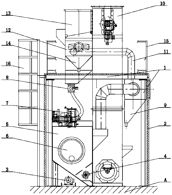
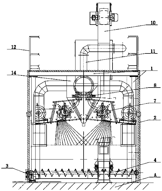
[0016] See Figure 1-Figure 2 As shown, the technical solution adopted in this specific embodiment is: it includes a steel structure platform 1, a noise reduction plate 2, a motor 3, a horizontal screw conveyor 4, a shot blasting chamber 5, an inlet and outlet pipe sealing device 6, a centrifugal shot blasting device 7. Pellet controller 8, settling box 9, bucket elevator 10, vacuum duct 11, storage box 12, pill slag separator 13, funnel 14, steel structure platform 1 with noise reduction board outside 2. There is a motor 3 on the left side of the bottom of the steel structure platform 1. The motor is set on the ground A, the output end of the motor 3 is connected with the horizontal screw conveyor 4, and the upper end of the horizontal screw conveyor 4 is connected with the shot blasting chamber 5. , The front end of the shot blasting chamber 5 is provided with an inlet and outlet pipe sealing device 6, and the upper end of the shot blasting chamber 5 is provided with a centri...


PUM


Abstract

The invention relates to the technical field of shot blasting derusting equipment, in particular to a pipeline shot blasting derusting machine. A noise reduction plate is arranged on the outer side ofa steel structure platform, a motor is arranged on the left side of the bottom of the steel structure platform, the output end of the motor is connected with a horizontal spiral conveyor, the upper end of the horizontal spiral conveyor is connected with a shot blasting chamber, the front end of the shot blasting chamber is provided with an inlet and outlet pipe sealing device, the right side of the bottom of the steel structure platform is provided with a settling box, and the left end of the settling box is connected with a bucket elevator; and one end of the bucket elevator is connected with the horizontal spiral conveyor, the other end of the bucket elevator is connected with a material storage box through a vacuum air pipe, the upper end of the material storage box is connected with ashot-slag separator, the shot-slag separator is arranged above the steel structure platform, and the bottom end of the material storage box is connected with a shot-leakage bucket. After the technical scheme is adopted, the pipeline shot blasting derusting machine has the beneficial effects that the machine can be installed without excavating of a foundation pit, field installation is facilitated, and industrial noise is greatly reduced.

Description

Technical field [0001] The invention relates to the technical field of shot blasting derusting equipment, in particular to a pipeline shot blasting derusting machine. Background technique [0002] The pipe shot blasting machine is the equipment used in the rust removal process during the coating operation of the steel pipe anticorrosive layer. The blast slag after the rust removal of the traditional pipe shot blasting machine is directly dropped into the bucket elevator, which requires shot blasting. There is a certain drop between the chamber and the bucket elevator. In order to ensure the height of this drop, it is usually necessary to set up a foundation work pit, which is difficult to install on site. The traditional pipeline shot blasting machine shot blasting rust removal operation, the working noise is loud, it is difficult to meet the requirements of environmental protection on the noise control of the workshop, and the noise pollution is not conducive to the control of t...

Claims


Application Information

Patent Timeline
IPC IPC(8): B24C1/08B24C3/04B24C9/00
CPCB24C1/086B24C3/04B24C9/00B24C9/006
Inventor 孙旭东孟宪俐王峰宾李跃超
Owner 廊坊市鼎盛机械设备有限公司
Learn More