
Pollution prevention and control system for mining wastelands

A wasteland and mine technology, applied in the field of mine wasteland pollution prevention and control system, can solve the problems of inability to prevent and control underground pollution sources, large engineering volume, complex construction, etc., and achieve good prevention and control effect, small engineering volume and short working hours Effect

Pending Publication Date: 2019-09-13
DALIAN DEETOP ENVIRONMENTAL TECH CO LTD
View PDF0 Cites 0 Cited by
  • Summary
  • Abstract
  • Description
  • Claims
  • Application Information

AI Technical Summary

Problems solved by technology

[0003] At present, there are in-situ remediation technology and ex-situ remediation technology for the treatment of such soil pollutants. For soil pollution below the groundwater level, the water washing method in the in-situ remediation technology is mainly used. The prevention and control method often used before and during the treatment is physical isolation, that is, designing a wall plate to prevent diffusion at the outer edge of the contaminated area, and pushing a large number of steel sheet piles into the ground continuously. This pollution prevention and control method not only improves soil pollution. The total cost required for restoration, while the construction is complicated, the project volume is large, and it takes a long time, and it is impossible to effectively prevent and control underground pollution sources in a timely manner

Method used


Image

  • Pollution prevention and control system for mining wastelands
  • Pollution prevention and control system for mining wastelands
  • Pollution prevention and control system for mining wastelands

Examples


Embodiment Construction

[0024] The technical solutions of the present invention will be clearly and completely described below in conjunction with the embodiments. Apparently, the described embodiments are only some of the embodiments of the present invention, not all of them. Based on the embodiments of the present invention, all other embodiments obtained by persons of ordinary skill in the art without making creative efforts belong to the protection scope of the present invention.

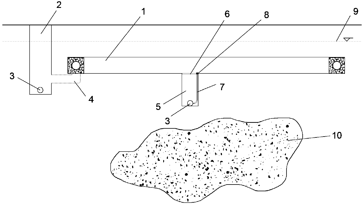
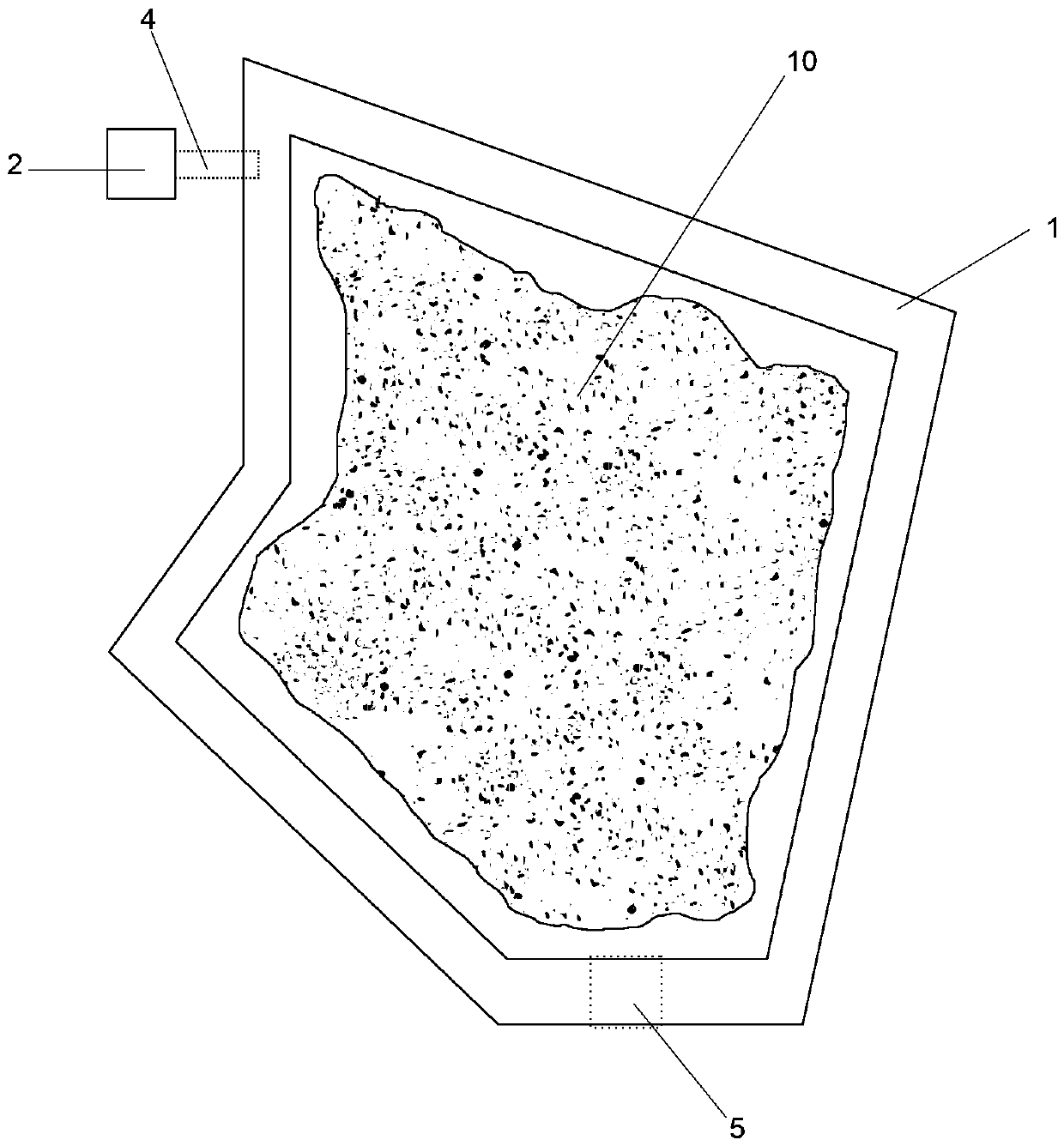
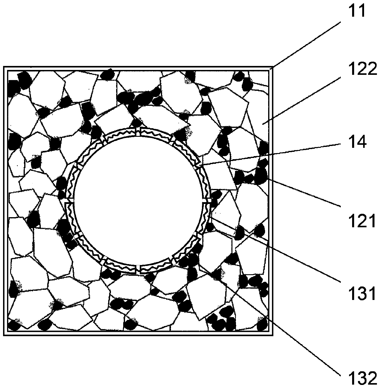
[0025] Such as Figure 1 to Figure 3 As shown, the present invention provides a pollution prevention and control system for abandoned mine sites, including: an annular water delivery culvert 1, a sump 2, a water pump 3, a connecting pipe 4, a water collection groove 5, and an impermeable cover plate 6. Pumping pipe 7, filter end 8, said annular water conveyance culvert 1 includes outer wall 11, filler 12, filter pipe 13, permeable hole 14, said sump 2 connects with annular water conveyance culvert through connecting pi...


PUM

PropertyMeasurementUnit
particle diameteraaaaaaaaaa
porosityaaaaaaaaaa

Abstract

The invention provides a pollution prevention and control system for mining wastelands. The system comprises an annular underground conveyance canal, a catch pit, water pumps, a communicating pipe, acatch groove, a waterproof cover plate, a pumping pipe and a filter end socket. The annular underground conveyance canal comprises an outer wall, a filler, a filter pipeline and a drainage hole. The catch pit is connected with the annular underground conveyance canal through the communicating pipe. The water pumps are respectively placed in the catch pit and the catch groove. The catch groove is directly connected with the annular underground conveyance canal. The waterproof cover plate and the filter end socket are both located between the annular underground conveyance canal and the catch groove. By designing the annular underground conveyance canal between the underground water level and a pollution source, the direction of water flow around the pollution source is changed, and pollutants are prevented from spreading in all directions with the flowing of underground water. In comparison with a traditional prevention and control method, the system of the invention has advantages of low work amount, short man-hour, low labor and material cost and good underground pollution source prevention and control effect.

Description

technical field [0001] The invention relates to the field of pollution prevention and control, in particular to a pollution prevention and control system for abandoned mine sites. Background technique [0002] In the process of mining, many mining activities such as mine drainage, leaching water produced by ore and waste rock piles, and random discharge of mining industry and domestic wastewater cause various pollutants such as volatile organic chlorine compounds, fuel oil, engine oil , dioxin or heavy metals such as cadmium, lead, copper, zinc, nickel, chromium and other organic and inorganic pollutants are deposited all year round, causing the pollution source to sink below the groundwater level. Under the action of groundwater, these pollutants are released from the gaps between soil particles As the groundwater diffuses into the surrounding soil, water and air, it will seriously endanger the soil environment of the mine and the health of the residents around the mine. ...

Claims


Application Information

Patent Timeline
Patent Type & Authority Applications(China)
IPC IPC(8): C02F9/02E03F5/10E03F5/22
CPCC02F9/00E03F5/10E03F5/22C02F1/001C02F1/28C02F1/44
Inventor 孙雅楠高树龙王酉宁赵小江
Owner DALIAN DEETOP ENVIRONMENTAL TECH CO LTD
Learn More