
Radiometer front end structure and terminal equipment

A technology of radiometer and chip, which is applied in the direction of radiometer effect, radiation pressure, optical radiation measurement, etc., can solve the problems of radiometer output voltage drift, difficult assembly, poor integration, etc., to reduce assembly difficulty, Achieve engineering and mass production, and reduce volume

Active Publication Date: 2019-09-13
THE 13TH RES INST OF CHINA ELECTRONICS TECH GRP CORP
View PDF8 Cites 2 Cited by
  • Summary
  • Abstract
  • Description
  • Claims
  • Application Information

AI Technical Summary

Problems solved by technology

[0005] In view of this, the embodiment of the present invention provides a radiometer front-end structure and terminal equipment to solve the problems of poor integration and difficult assembly in the prior art, and changes in the ambient temperature will cause the radiometer output voltage to produce significant changes. The problem of voltage drift

Method used


Image

  • Radiometer front end structure and terminal equipment
  • Radiometer front end structure and terminal equipment
  • Radiometer front end structure and terminal equipment

Examples


Embodiment Construction

[0042] In the following description, specific details such as specific system structures and technologies are presented for the purpose of illustration rather than limitation, so as to thoroughly understand the embodiments of the present invention. It will be apparent, however, to one skilled in the art that the invention may be practiced in other embodiments without these specific details. In other instances, detailed descriptions of well-known systems, devices, circuits, and methods are omitted so as not to obscure the description of the present invention with unnecessary detail.

[0043] In order to illustrate the technical solutions of the present invention, specific examples are used below to illustrate.

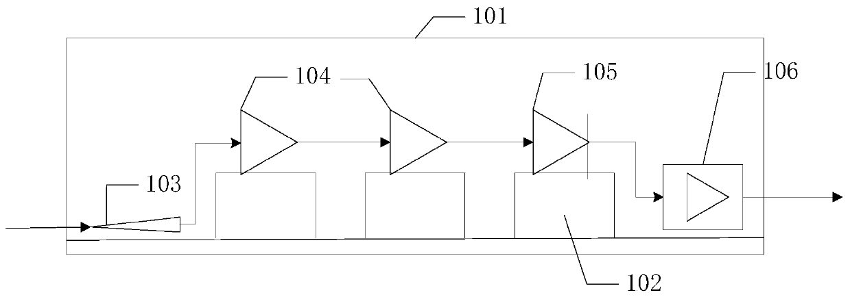
[0044] figure 1 The schematic diagram of the front-end structure of the radiometer provided by the embodiment of the present invention is described in detail as follows.

[0045] The radiometer front-end structure may include: a metal box 101 , a boss 102 , a quartz p...


PUM


Abstract

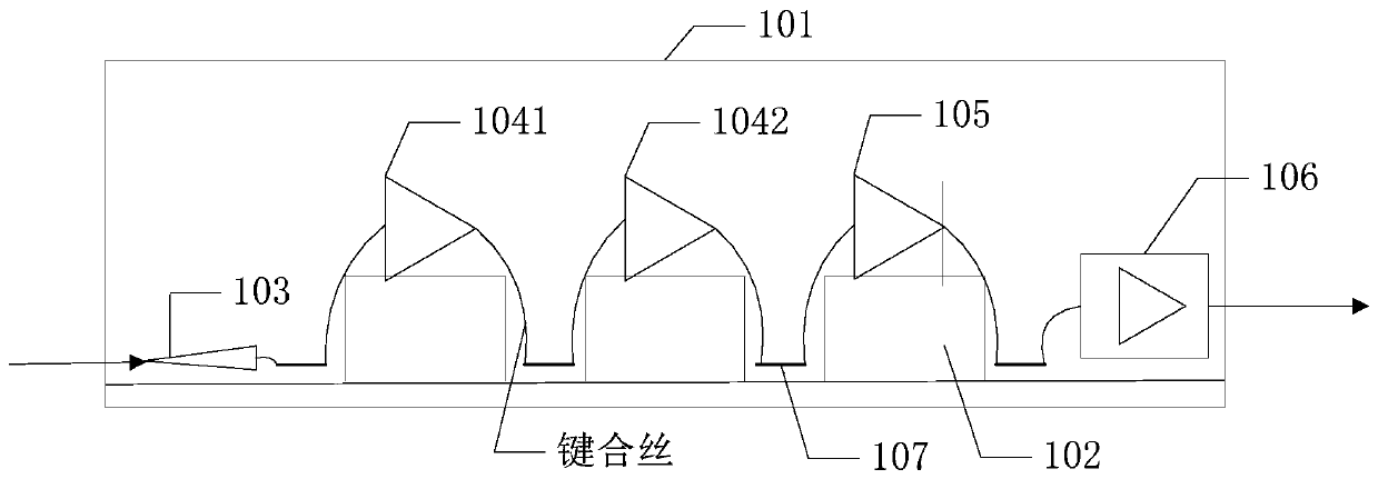
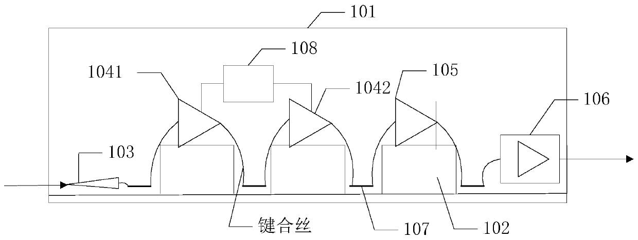
The invention is applicable to the technical fields of terahertz security inspection, substance detection, remote sensing, medical diagnosis and the like, and provides a radiometer front end structureand terminal equipment. The structure comprises a metal box body, a two-stage low noise amplifier chip, a detector chip, a quartz probe and a video amplifier, wherein a groove is formed in the upperside of the metal box body, a plurality of bosses are arranged in the groove, and the bosses are used for positioning the chips; the two-stage low noise amplifier chip and the detector chip are sequentially arranged on the corresponding bosses; the quartz probe is arranged in the groove of the metal box body, is located on the left side of the boss corresponding to the two-stage low noise amplifier chip, and is used for receiving signals radiated by objects; and the video amplifier is arranged in the groove of the metal box body and located on the right side of the boss corresponding to the detector chip. The adjacent devices are in electrical connection with each other, so that the volume of each circuit can be significantly reduced, the advantages of high integration level and fully-automatic assembly can be realized, the assembly difficulty can be reduced, and the engineering manufacture and batch production can be achieved.

Description

technical field [0001] The invention belongs to the technical fields of terahertz security inspection, material detection, remote sensing and medical diagnosis, and in particular relates to a radiometer front-end structure and terminal equipment. Background technique [0002] A radiometer is a high-sensitivity receiver used to measure the thermal radiation of objects and is the main tool for passive microwave remote sensing. At present, microwave radiometers based on ground-based (including ground and ship-borne platforms), space-based (including aircraft, missile, balloon platforms), satellite-based (including satellite, spacecraft, space shuttle platforms) and other carrier platforms have been developed rapidly. The radiometer has also developed from the meter-wave radiometer to the current millimeter-wave, sub-millimeter-wave and even terahertz radiometers. Terahertz can pass through non-metallic and non-polar materials with little attenuation, and realize terahertz imag...

Claims


Application Information

Patent Timeline
Patent Type & Authority Applications(China)
IPC IPC(8): G01J5/46G01J5/00G01J5/02
CPCG01J5/46G01J5/00G01J2005/0077G01J5/068
Inventor 周彪任玉兴孔令甲胡丹王建高长征赵瑞华徐达
Owner THE 13TH RES INST OF CHINA ELECTRONICS TECH GRP CORP
Learn More