Feed-sideways waveguide conversion structure with suspended strip line

A technology of waveguide conversion and strip line, which is applied in the direction of waveguide devices, connecting devices, electrical components, etc., can solve the problems of damaged microstrip circuits, low insertion loss, high return loss, etc., to ensure positional accuracy and dimensional accuracy, and ensure Stability and reliability, easy system integration effects

Inactive Publication Date: 2019-09-13
LINGBAYI ELECTRONICS GRP
View PDF3 Cites 7 Cited by
  • Summary
  • Abstract
  • Description
  • Claims
  • Application Information

AI Technical Summary

Problems solved by technology

Among them, the transition processing of the ridge waveguide is complicated, and the assembly tolerance is strict. The contact point between the ridge and the microstrip circuit has a great influence on the performance of the entire transition circuit. Too loose will affect the circuit performance, and too tight will damage the microstrip circuit. Repeatable Poor performance and inconvenient disassembly
It is difficult to suppress all unwanted feedback due to the various modes of the fin line transition to the spine fin line, and the input and output fin lines provide a purely reactive source or load impedance at the cutoff frequency, which puts the active device in an undesired state. Stable region, prone to self-oscillation
The common coupling probe transition is microstrip probe coupling, which has low insertion loss, high return loss, wide frequency band, and compact structure, but because of the opening on the side wall of the waveguide to insert the microstrip probe, this The tightness of the transition mode is poor

Method used


Image

  • Feed-sideways waveguide conversion structure with suspended strip line
  • Feed-sideways waveguide conversion structure with suspended strip line
  • Feed-sideways waveguide conversion structure with suspended strip line

Examples


Embodiment Construction

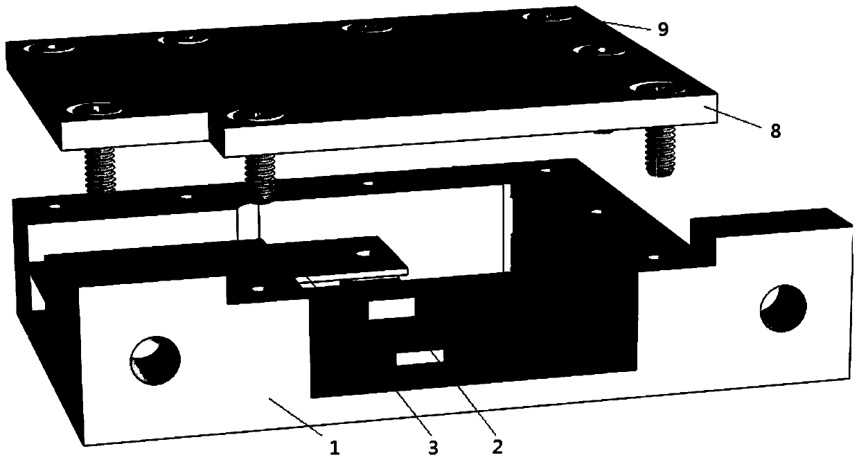
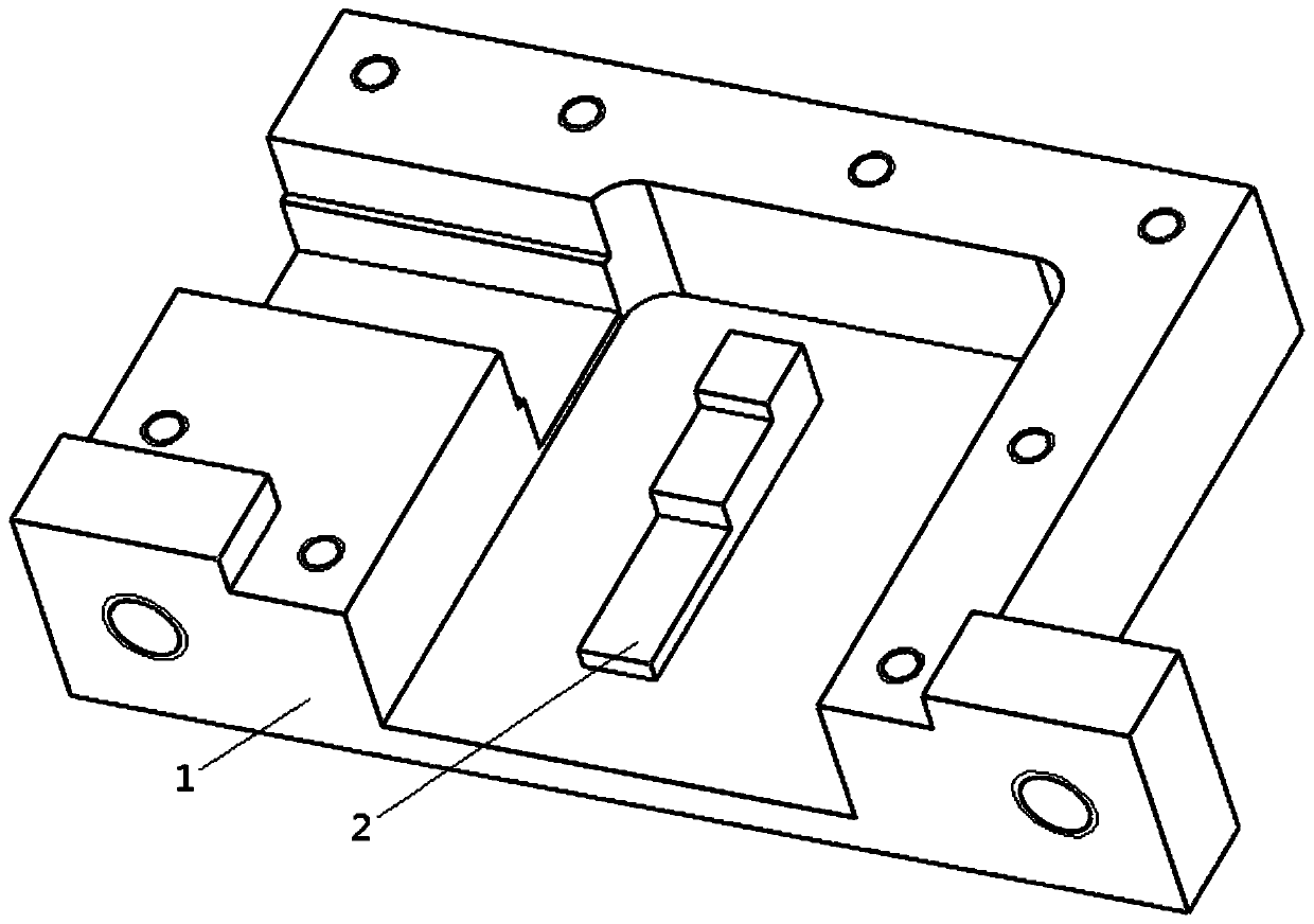
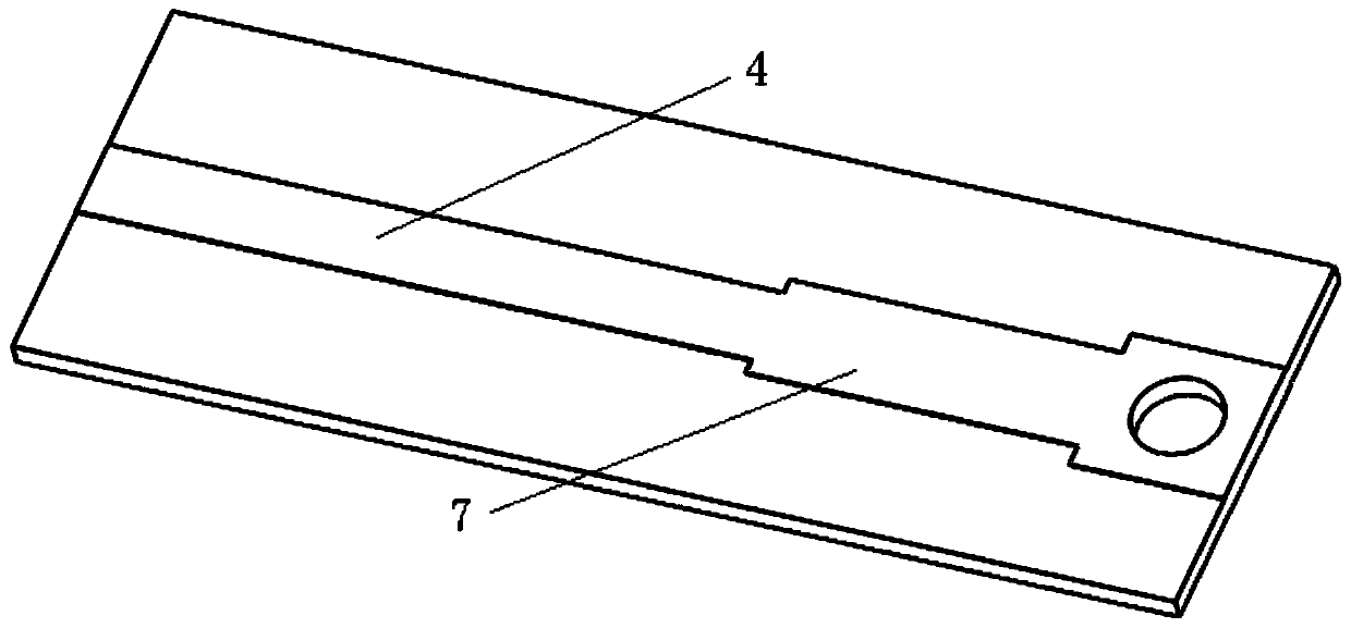
[0024] refer to Figure 1-Figure 4 . In the embodiment described below, a side-fed suspended stripline waveguide conversion structure includes: a rectangular waveguide 1 with a narrow slot on the wide wall and a microstrip dielectric plate 3 inserted into the slot of the narrow slot body, the cover Plate 8 and bolt 9. Wherein: the microstrip dielectric plate 3 extends into the stepped waveguide ridge 2 suspended in the microstrip cavity through the slot, and the extension part is the microstrip dielectric plate 3 and the suspended strip line 4, the impedance changer 7, The connection pad 6 and the stepped waveguide ridge 2 are finally guided to the inner wall of the wide side of the waveguide, and the energy conversion is realized by magnetic coupling. The stepped waveguide ridge 2 is parasitic fixed on the bottom plate in the waveguide cavity, and the suspended strip line 4 is along the narrow slot port. The upper surface of the microstrip dielectric plate 3 extends to feed...


PUM


Abstract

The invention discloses a feed-sideways waveguide conversion structure with a suspended strip line and aims at providing a conversion structure which is wide in band, low in insertion loss and compactin structure. The feed-sideways waveguide conversion structure is achieved through the technical scheme as follows: a microstrip dielectric plate (3) extends to a step waveguide ridge (2) in a suspended microstrip cavity through a slit; an extension part is provided with the microstrip dielectric plate (3), the suspended strip line (4), an impedance transformer (7), a connection pad (6) and the step waveguide ridge (2) and is finally guided to an inner wall at a wide side of a waveguide to achieve energy conversion in a magnetic coupling manner, wherein the suspended strip line (4), the impedance transformer (7), the connection pad (6) and the step waveguide ridge (2) are arranged on the microstrip dielectric plate (3); the step waveguide ridge is parasitically fixed on a bottom plate ina waveguide cavity; the suspended strip line (4) extends along the upper surface of the microstrip dielectric plate from a port of a narrow slot and feeds electricity from the side surface of the waveguide cavity; and the correspondingly connected impedance transformer (7) and connection pad (6) are magnetically coupled to a transitional section structure and are matched with the step waveguide ridge through a quarter wavelength impedance transformer, thereby forming the waveguide conversion structure, with the suspended strip line, capable of inputting and outputting electromagnetic field energy in a feed-sideways manner.

Description

technical field [0001] The invention relates to a suspended strip line waveguide conversion structure applied to antennas, feed networks and microwave devices. Background technique [0002] The waveguide-microstrip transition circuit is an important structure connecting the planar circuit and the waveguide in millimeter-wave and terahertz systems, which directly affects the system performance. Microstrip line is an important transmission line in millimeter wave and terahertz integrated circuits, and each monolithic microwave integrated circuit (MMIC) is mainly connected by microstrip line. Due to the narrow frequency band of the microstrip antenna itself, it is easy to cause surface waves and other shortcomings, so in the submillimeter wave electronic system, the suspended substrate strip line is widely used as the transmission line, but the submillimeter wave test system and other submillimeter wave systems are not An RF interface that makes extensive use of standard recta...

Claims


Application Information

Patent Timeline
Patent Type & Authority Applications(China)
IPC IPC(8): H01P5/107
CPCH01P5/107
Inventor 汪波王碧呈曾传宝赵玉国许小玲
Owner LINGBAYI ELECTRONICS GRP
Why Eureka
Try Eureka