Thermal interface material, interface thermal coupling method, and production method for thermal interface material
A manufacturing method, thermal bonding technology, applied in heat exchange materials, chemical instruments and methods, cooling/ventilation/heating transformation, etc.
- Summary
- Abstract
- Description
- Claims
- Application Information
AI Technical Summary
Problems solved by technology
Method used
Image
Examples
Embodiment 1~6
[0094] Six types (A to F) of graphite films were produced by the above method. The HTT, thickness, thermal conductivity, and density at the time of fabrication are as follows.
[0095] (A)HTT: 2900°C, thickness 14.6μm, thermal conductivity in film direction: 1810W / mK, density 2.0g / cm 3
[0096] (B)HTT: 2900°C, thickness: 7.3μm, thermal conductivity in the film direction: 1780W / mK, density 2.0g / cm 3
[0097] (C)HTT: 2900°C, thickness: 2.7μm, thermal conductivity in the film direction: 1700W / mK, density 2.0g / cm 3
[0098] (D)HTT: 2900°C, thickness: 1.0μm, thermal conductivity in the film direction: 1700W / mK, density 2.0g / cm 3
[0099] (E)HTT: 2900°C, thickness: 0.3μm, thermal conductivity in the film direction: 1610W / mK, density 1.9g / cm 3
[0100] (F)HTT: 2900℃, Thickness: 0.1μm, Thermal conductivity in film direction: 1620W / mK, Density: 1.9g / cm 3
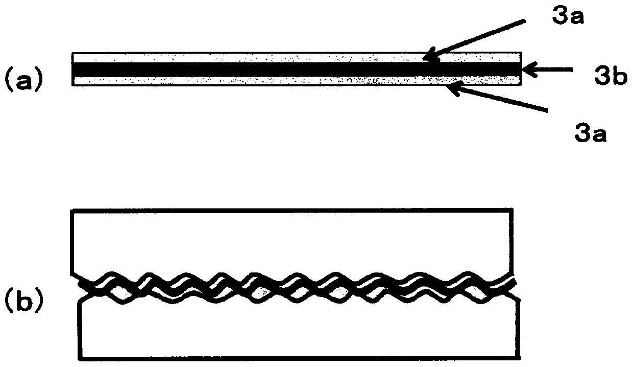
[0101] A flexible acrylic layer (thickness 1 μm) was formed on both surfaces of the aforementioned (A) to (F), and used a...
Embodiment 8~10
[0114] Three types of graphite thin films were prepared by changing the maximum treatment temperature (HTT) of (B) used in the examples. Flexible layers (thickness: 10 μm) were formed on both surfaces using an acrylic polymer as a flexible material, and the thermal resistance characteristics were measured by the same method as in Examples 1 to 7. The results are shown in Table 3.
[0115] (B-2) HTT: 2700°C, Thickness: 7.3μm, Thermal conductivity in film direction: 1280W / mK, Density: 2.0g / cm 3
[0116] (B-3)HTT: 2600°C, thickness: 7.3μm, thermal conductivity in the film direction: 1080W / mK, density 1.9g / cm 3
[0117] (B-4)HTT: 2400°C, Thickness: 7.3μm, Thermal conductivity in film direction: 580W / mK, Density: 1.7g / cm 3
[0118] [table 3]
[0119]
[0120] From this result, it can be seen that the thermal conductivity in the plane direction of the graphite film has a great influence on the TIM characteristics. In order to achieve low thermal resistance characteristics, ...
Embodiment 11~16
[0122] Using the graphite thin film (E), six types of TIMs in which the type and thickness of the flexible layer were changed were fabricated. Table 4 shows the results of measuring the thermal resistance characteristics by the same method as in the above-mentioned examples. From this result, it can be seen that the type of the flexible material has little influence on the thermal resistance characteristics, and the weight ratio of the flexible material to the graphite film (flexible material / graphite film) is preferably in the range of 0.08 to 25 (preferably 1 to 20).
[0123] [Table 4]
[0124]
PUM
| Property | Measurement | Unit |
|---|---|---|
| thickness | aaaaa | aaaaa |
| density | aaaaa | aaaaa |
| boiling point | aaaaa | aaaaa |
Abstract
Description
Claims
Application Information
 - R&D
- Intellectual Property
- Life Sciences
- Materials
- Tech Scout
- Unparalleled Data Quality
- Higher Quality Content
- 60% Fewer Hallucinations
Browse by: Latest US Patents, China's latest patents, Technical Efficacy Thesaurus, Application Domain, Technology Topic, Popular Technical Reports.
© 2025 PatSnap. All rights reserved.Legal|Privacy policy|Modern Slavery Act Transparency Statement|Sitemap|About US| Contact US: help@patsnap.com


