Using method for movable riverway sludge dredging device

A mobile, river technology, applied to mechanically driven excavators/dredgers, earth movers/shovels, construction, etc., can solve the problem of changing draft depth, unstable equipment center, and unsuitable dredging devices for large rivers and other problems to achieve the effect of avoiding motor damage

Active Publication Date: 2019-09-20
杨滨
View PDF12 Cites 2 Cited by
  • Summary
  • Abstract
  • Description
  • Claims
  • Application Information

AI Technical Summary

Problems solved by technology

The existing problem is: use the movement of the hull to drive the scraper forward to scrape the river bottom silt into the scraper box, the river bottom is not flat, there may be not only a mud layer, but also a rock layer, so the scraper is not necessarily Can achieve the purpose of the invention of the patent
The existing problem is that the dredging device is installed on the slider on the fixed device through a cross bar, the dredging device moves left and right along the fixed device, and the fixed device is installed on the bank of the river, such a dredging device cannot be applied to large rivers Medium, only suitable for small rivers, can be fixed on the bank
The existing problems are: the adopted silt pumping device is mainly driven by the submersible motor to drive the winch, and then the silt is sucked onto the hull through the suction pipe. Firstly, this process causes the silt in the river channel to be muddied as a whole, seriously affecting the normal life of the organisms in it. Survival destroys the natural ecology; the second is that the reamer can only cut it into fragments when encountering rock layers, and the fragments cannot be sucked into the hull by the straw, so the rock layers or large stones cannot be dredged out, it cannot meet the needs of the site; moreover, without underwater positioning, the bottom of the river cannot be cleaned evenly and

Method used


Image

  • Using method for movable riverway sludge dredging device
  • Using method for movable riverway sludge dredging device
  • Using method for movable riverway sludge dredging device

Examples


Embodiment 1

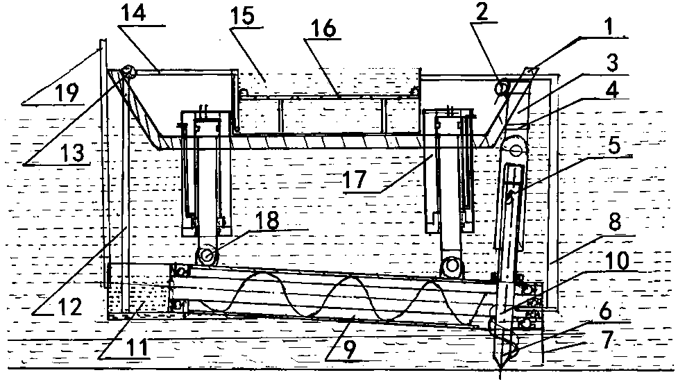
[0041] Embodiment 1, with reference to attached figure 1 , a mobile river sludge dredging device mentioned in the present invention includes a movable hull 1 and a sludge dredging device, and the sludge dredging device includes a power machine 2, a transmission connecting shaft 3, a universal joint 4, a spline shaft 5. Silt agitator 6, water circulation pipe 8, double-capacity mixer 9, turbine drive 10, sewage storage tank 11, sewage siphon 12, sewage pump 13, sewage pump outlet pipe 14, sludge treatment tank 15, multi-stage pollution reduction device 16, lifting hydraulic cylinder 17, adjustment shaft 18, the power machine 2 is installed at the bow of the movable hull 1, connected to the spline sleeve through the transmission connection shaft 3 and the universal joint 4, and the spline sleeve is movably connected to the spline sleeve. The key shaft 5, the lower end of the spline shaft 5 is connected to the mud agitator 6, and the mud agitator 6 provides power to the double-ca...

Embodiment 2

[0064] Embodiment 2, the technical scheme mentioned in the present invention is compared with embodiment 1, and difference is:

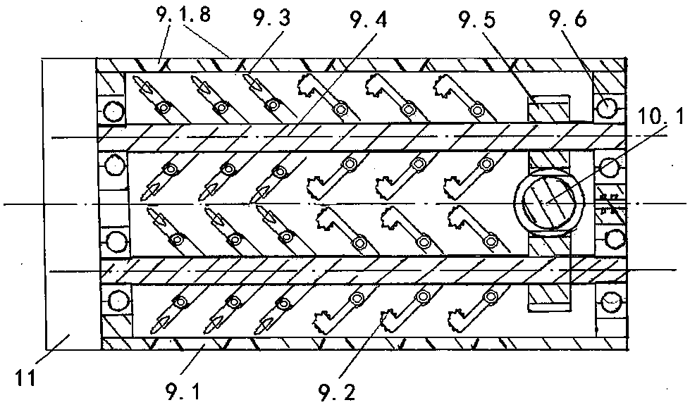
[0065] Refer to attached Figure 10 The conveying plummet 9.2 mentioned in the present invention includes a plummet head 9.2.1, a plummet rod 9.2.2, a side plummet sawtooth 9.2.3, and a main plummet sawtooth 9.2.4. The plummet rod 9.2.2 The lower end is provided with a pin hole, and the upper end is provided with a pendent head 9.2.1 front and rear. The front end of the pendent head 9.2.1 is provided with a main pendent saw tooth 9.2.4, and the outer wall is evenly provided with a side pendent saw tooth 9.2.3. The conveying hammers with hammerheads at the front and rear, and the sawtooth structure can hammer the stones more evenly, and its crushing effect is better than that of a single head; in addition, the side suspension hammer provided by the present invention Hammer sawtooth 9.2.3 and main plummet sawtooth 9.2.4 can be made of diamond material...

Embodiment 3

[0066] Embodiment 3, the technical scheme that the present invention mentions compares with embodiment 1 and 2, and difference is:

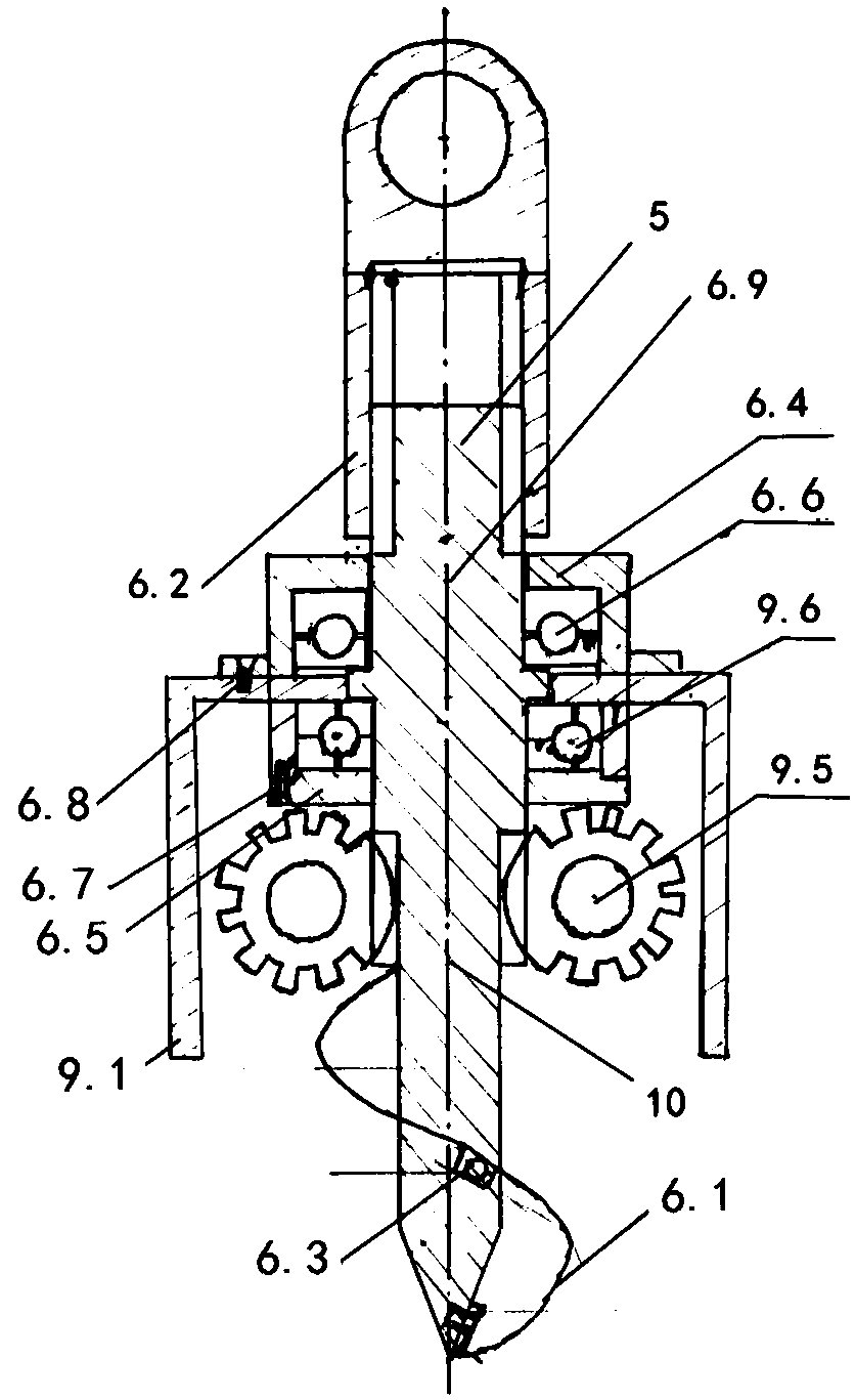
[0067] Refer to attached Figure 11 , The sludge agitator 6 of the present invention comprises stirring suspension blade 6.1, spline sleeve 6.2, suspension blade fixing bolt 6.3, pressure bearing pressure cap 6.4, rolling bearing pressure cap 6.5, pressure bearing 6.6, lower pressure cap bolt 6.7, upper pressure cap bolt 6.8. Agitating main shaft 6.9, the upper end of said agitating main shaft 6.9 is connected with spline shaft 5 and spline sleeve 6.2, and the upper middle part of agitating main shaft 6.9 is connected with double-capacity mixer housing 9.1 through rolling bearing pressure cap 6.5 and pressure bearing 6.6, The lower side of the middle part of the agitating main shaft 6.9 engages the transmission gear 9.5 through the turbine driver 10, and the lower end of the agitating main shaft 6.9 is connected to the agitating suspension blade ...


PUM


Abstract

The invention relates to a using method for a movable riverway sludge dredging device. According to the technical scheme, a movable hull and the sludge dredging device are included, a sludge agitator and a double-capacity mixer are used to fully mix the sludge at the bottom of a river with the river water to make the mixture into sewage, a suspending hammer at the front half part of the double-capacity mixer crushes the bulk material which is stirred out at the bottom of the river, and then a soft material such as a plastic bag or a rope is cut by a suspending slicing piece at the rear half part of the double-capacity mixer, so that the generated small-particle sewage is transported to a sewage storage tank in the form of fluid and then is pumped into the sludge treatment tank on the movable hull under the pumping action of a sewage pump for treatment, and the circulating water is sprayed to an inlet of the double-capacity mixer to drive the sludge into the double-capacity mixer to form a circulation. The using method has the beneficial effects that the riverway can be smoothly cleaned, the ecological impact on the riverway is very small, a lot of man-hours can be saved, and the serious influence on the use of the riverway and the traffic is unlikely; and in addition, compared to an existing dredging device, by the adoption of the using method, the efficiency is higher and the cleaning is thorough.

Description

technical field [0001] The invention relates to a sludge dredging device and method, in particular to a method for using a mobile river sludge dredging device. Background technique [0002] At present, in the dredging of the river channel, the method often used is: firstly block the original river channel, then drain the water in this section of the river channel, and finally use mechanical methods to clean it up. use. In this way, it is not only time-consuming and labor-intensive, but also has a serious impact on the ecological system in the river. At the same time, sometimes for the safety of construction, it is necessary to temporarily close the traffic line adjacent to the river, which seriously affects the traffic in the corresponding section. ; and this method does not apply to large rivers. [0003] The Chinese patent document publication number is 207749557U, and the patent title is "A kind of dredging equipment for river silt", which includes a hull and a dredging...

Claims


Application Information

Patent Timeline
IPC IPC(8): E02F5/28E02F3/92E02F7/00E02F7/10
CPCE02F3/9225E02F3/9293E02F5/282E02F7/005E02F7/10
Inventor 杨滨冯思远赵俊强
Owner 杨滨
Why Eureka
Try Eureka