Mechanical arm kinematics parameter calibration method based on measuring of laser tracker

A technology of kinematic parameters and laser tracker, which is applied to manipulators, program-controlled manipulators, manufacturing tools, etc., can solve problems such as poor space adaptability, unaccounted for errors, and difficulty in measuring terminal attitudes

Inactive Publication Date: 2019-09-27
DALIAN UNIV OF TECH
View PDF7 Cites 27 Cited by
  • Summary
  • Abstract
  • Description
  • Claims
  • Application Information

AI Technical Summary

Problems solved by technology

[0005] The purpose of the present invention is to overcome the defects and deficiencies of the existing industrial manipulator arm kinematics parameter calibration method, suc

Method used


Image

  • Mechanical arm kinematics parameter calibration method based on measuring of laser tracker
  • Mechanical arm kinematics parameter calibration method based on measuring of laser tracker
  • Mechanical arm kinematics parameter calibration method based on measuring of laser tracker

Examples


Embodiment Construction

[0070] The specific embodiments of the present invention will be described in detail below in conjunction with the technical solutions and accompanying drawings.

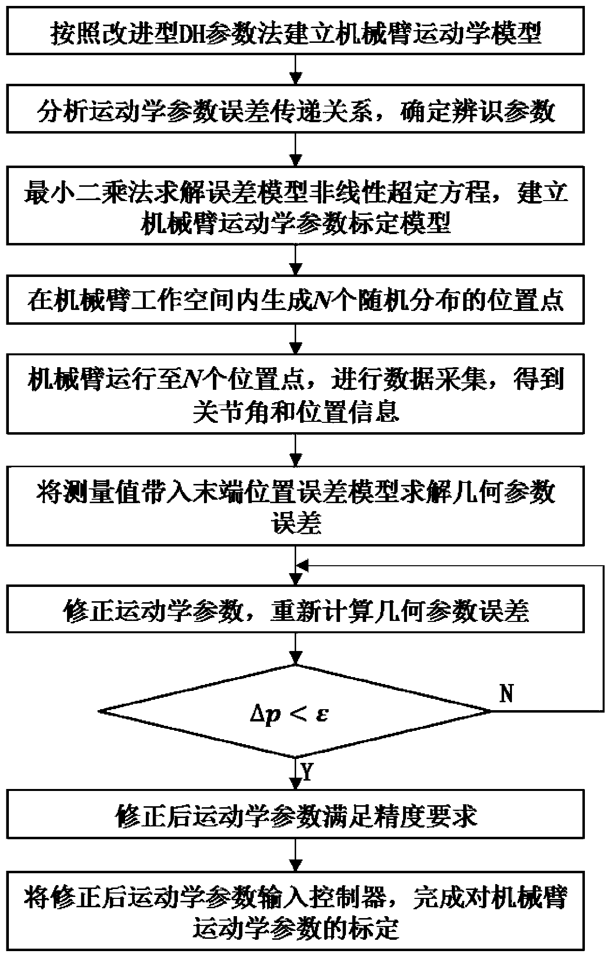
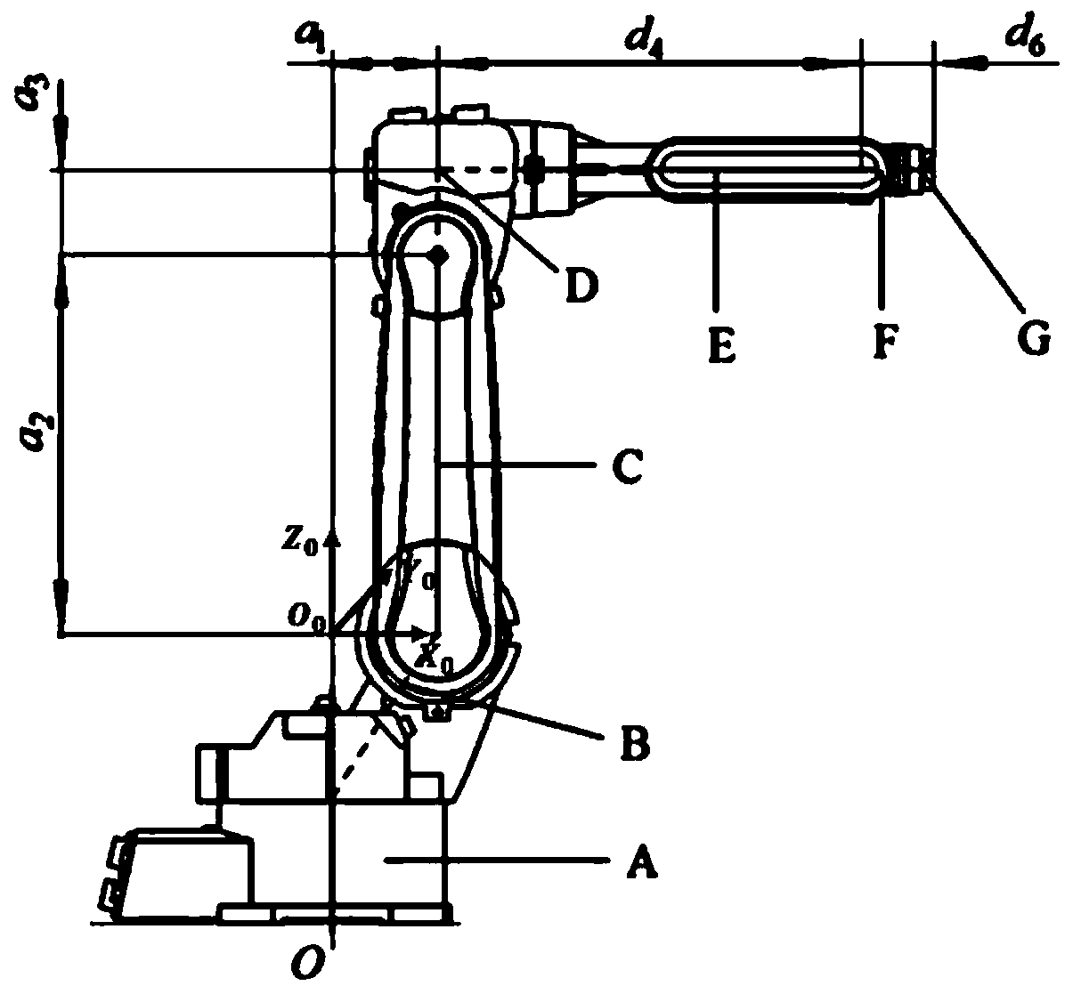
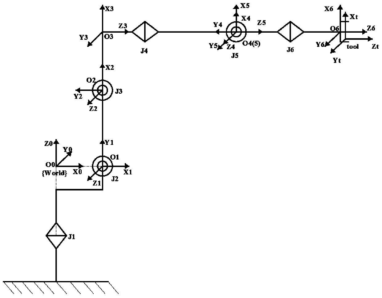
[0071] attached figure 1 It is a flow chart of the method for calibrating the kinematics parameters of the manipulator based on laser tracker measurement in the present invention, with figure 2 It is a schematic diagram of the structure of the articulated six-degree-of-freedom manipulator, and the joint coordinate system of the articulated six-degree-of-freedom manipulator is as attached image 3 As shown, the layout of the Leica laser tracker and the mechanical arm at the measurement site in this embodiment is as attached Figure 4 As shown, the target ball adapter plate used at the end of the industrial robot arm is as attached Figure 5 shown. The specific steps of the calibration method flow are as follows:

[0072] Step 1: Construction of the kinematics model of the six-degree-of-freedom articulated manipu...


PUM


Abstract

The invention discloses a mechanical arm kinematics parameter calibration method based on measuring of a laser tracker, and belongs to the field of industrial mechanical arm kinematics, and relates to the mechanical arm kinematics parameter calibration method based on measuring of the laser tracker. The method is based on the mechanical arm joint construction. An improved DH parameter method is adopted for building a mechanical arm kinematics model, a kinematics modeling result is used for building a mechanical arm kinematics parameter error calibration model, in consideration with the mechanical arm three-dimensional space work range, the laser tracker is adopted for measuring N absolute position coordinates of the tail end of the mechanical arm, on the basis of the kinematics parameter error calibration model, through repeated iteration, the mechanical arm kinematics parameter error is solved, a corrected kinematics parameter is input into a mechanical arm controller, and offline calibration of the mechanical arm is achieved; the mechanical arm tail end position measuring method is high in robustness, high in speed, and high in process automation degree, the adopted error solving method is high in speed, high in precision and simple in process, and the high-precision rapid calibration of joint type mechanical arm kinematics parameters can be achieved.

Description

technical field [0001] The invention belongs to the field of kinematics of industrial manipulators, and relates to a method for calibrating kinematics parameters of a manipulator based on a laser tracker. Background technique [0002] Multi-degree-of-freedom industrial manipulators are widely used in many fields such as aerospace, medicine, and industrial production due to their advantages of high flexibility, strong maneuverability, and wide range of space. The performance of industrial robotic arms (such as motion accuracy, positioning accuracy, etc.) directly affects its application in the field of precision machining. Among them, the absolute positioning accuracy of the end is one of the important indicators for evaluating the performance of industrial manipulators. After in-depth research by domestic and foreign scholars, the repeat positioning accuracy of the end of industrial manipulators has been greatly improved. However, due to the cumulative error in manipulator ...

Claims


Application Information

Patent Timeline
IPC IPC(8): B25J9/16
CPCB25J9/1605
Inventor 马建伟闫惠腾高松贾振元王嘉丞司立坤
Owner DALIAN UNIV OF TECH
Why Eureka
Try Eureka