Evaporating cavity lining device, evaporating system thereof and evaporating device

An evaporation device and lining technology, which is applied in the field of semiconductor technology, can solve the problems of high cost of crystal oscillator devices, material leakage, and interference with material evaporation rate, etc.

Active Publication Date: 2019-09-27
SUZHOU QUINGYUE OPTOELECTRONICS TECH CO LTD
View PDF5 Cites 0 Cited by
  • Summary
  • Abstract
  • Description
  • Claims
  • Application Information

AI Technical Summary

Problems solved by technology

[0004] The purpose of the present invention is to overcome the point source evaporation equipment in the prior art. When the material is exhausted and the source needs to be replaced, the material temperature rises for a long time, the material evaporation rate stabilizes for a long time, the cost of using a crystal oscillator is high, and material leakage is prone to occur. The problem of monitoring the evaporation rate of materials by interfering with the crystal oscillator device

Method used


Image

  • Evaporating cavity lining device, evaporating system thereof and evaporating device
  • Evaporating cavity lining device, evaporating system thereof and evaporating device

Examples


Embodiment 1

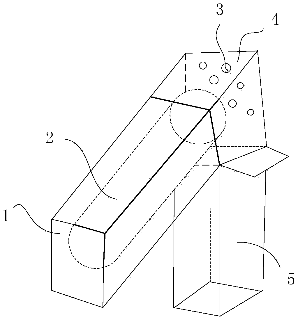
[0046] This embodiment provides an evaporation chamber lining device, such as figure 1 As shown, it includes a chamber assembly 1, and the chamber assembly 1 includes, a first housing, which has a first open end and a second open end oppositely arranged, and the first open end is externally connected to an evaporating device 6, and the A steam channel 2 suitable for steam circulation is formed in the first housing; a second housing is communicated with the second open end, and a material retention area 4 for retaining steam from the steam channel 2 is formed in the second housing .

[0047] Further, a recovery device 5 is also included, which communicates with the bottom of the second casing, so that the materials in the material storage area 4 can be recovered into the recovery device 5 without worrying that the materials will pollute the overall evaporation environment. Preferably, the recovery device 5 is in detachable communication with the second housing. The present in...

Embodiment 2

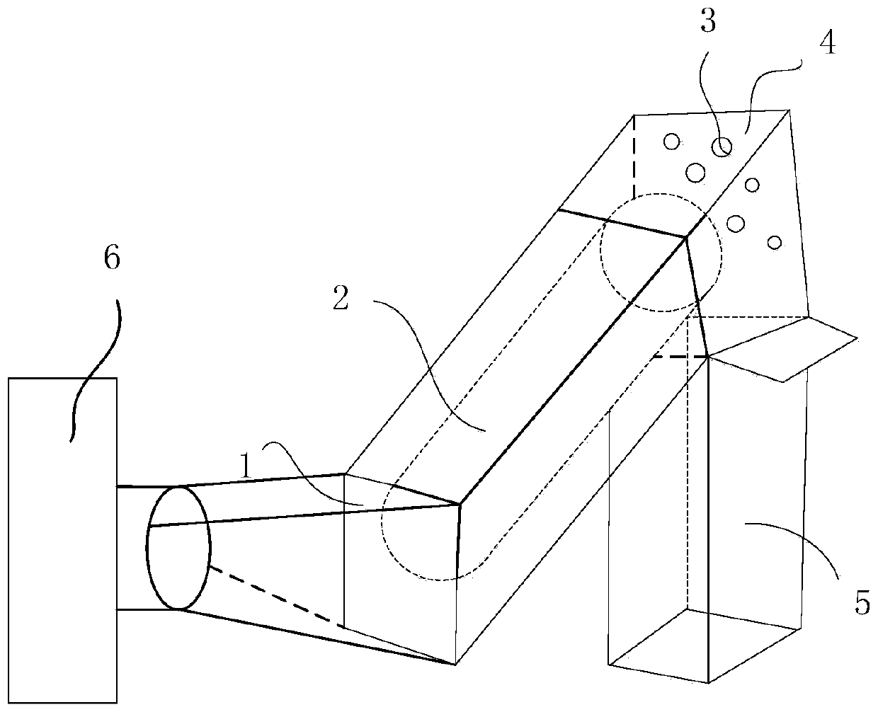
[0051] This embodiment provides an evaporation chamber lining device. On the basis of the above-mentioned embodiment 1, it also includes a heating assembly, which is arranged on the steam channel 2 to heat the material remaining on the inner wall of the steam channel 2. And make it into the material retention area. This embodiment does not specifically limit the specific structure of the heating assembly. Optionally, the heating assembly is an annular heating assembly, and the annular heating assembly is wound on the first casing to Steam channel 2 is heated. Optionally, the annular heating component may be a heating wire or a heating rod. Optionally, the shape of the heating wire may be wavy, helical or a combination of wavy and helical.

[0052] Further, such as figure 2 As shown, the evaporation device 6 is set to heat up the organic material for evaporation. The present invention does not specifically limit the structure of the evaporation device 6, as long as the orga...

Embodiment 3

[0054] This embodiment provides an evaporation chamber lining device. On the basis of the above-mentioned embodiments 1 and 2, the shape of the first casing is a cuboid; the shape of the second casing is a cuboid or a cube; The shape of the recovery device 5 is a cuboid. Optionally, the first housing, the second housing and the recovery device 5 may also be circular or cube structures. Optionally, the materials of the first casing, the second casing and the recovery device 5 are all stainless steel.


PUM


Abstract

The invention relates to the technical field of semiconductor technology, in particular to an evaporating cavity lining device, an evaporating system thereof and an evaporating device. The evaporating cavity lining device comprises a cavity assembly, wherein the cavity assembly comprises a first shell and a second shell; the first shell is provided with a first opening end and a second opening end arranged oppositely; the first opening end is externally connected with the evaporating device; a steam passage allowing steam to circulate is formed in the first shell; the second shell communicates with the second opening end; and a material storing area for storing the steam from the steam passage is formed in the second shell. The evaporating cavity lining device can ensure that the evaporating device warms organic material in advance, and the situation that the evaporated material enters an evaporating area to interfere with a base plate is avoided.

Description

technical field [0001] The invention relates to the technical field of semiconductor technology, in particular to an evaporation chamber lining device, an evaporation system, and an evaporation device. Background technique [0002] Organic Light-Emitting Diode (OLED), also known as organic electric laser display, organic light-emitting semiconductor, is a device that uses a multilayer organic thin film structure to generate electroluminescence. OLED has a wide viewing angle, high contrast, and low power consumption. The advantages of electricity, fast response, and wide operating temperature range have attracted widespread attention in the display field. [0003] OLED luminescence needs to evaporate several layers of organic materials between the substrate and the packaging mechanism. The evaporation devices are divided into point source evaporation equipment and line source evaporation equipment. Add organic materials, vacuumize to a high vacuum environment, heat the cruci...

Claims


Application Information

Patent Timeline
Patent Type & Authority Applications(China)
IPC IPC(8): C23C14/26C23C14/12
CPCC23C14/12C23C14/26
Inventor 于子洋葛鹏程廖明富
Owner SUZHOU QUINGYUE OPTOELECTRONICS TECH CO LTD
Why Eureka
Try Eureka