Drilling fluid circulation system for reducing drilling trip-out suction pressure

A technology of circulation system and drilling fluid, applied in the automatic control system of drilling, drilling equipment, wellbore/well components, etc., can solve the problems of prolonging the exposure time of the open-hole section, increasing the risk of wellbore instability, and increasing the cost of drilling time. , to reduce the risk of wellbore instability, reduce tripping time, and reduce drilling costs.

Active Publication Date: 2019-09-27
YANGTZE UNIVERSITY
View PDF9 Cites 4 Cited by
  • Summary
  • Abstract
  • Description
  • Claims
  • Application Information

AI Technical Summary

Problems solved by technology

This results in a long tripping time for deep wells, ultra-deep wells, and extended-reach horizontal wells, which not only increases the time cost of drilling, but also prolongs the exposure time of the open hole section and increases the risk of wellbore instability

Method used


Image

  • Drilling fluid circulation system for reducing drilling trip-out suction pressure
  • Drilling fluid circulation system for reducing drilling trip-out suction pressure
  • Drilling fluid circulation system for reducing drilling trip-out suction pressure

Examples


Embodiment Construction

[0024] In order to make the purpose, technical solution and advantages of the present invention clearer, the embodiments of the present invention will be further described below in conjunction with the accompanying drawings.

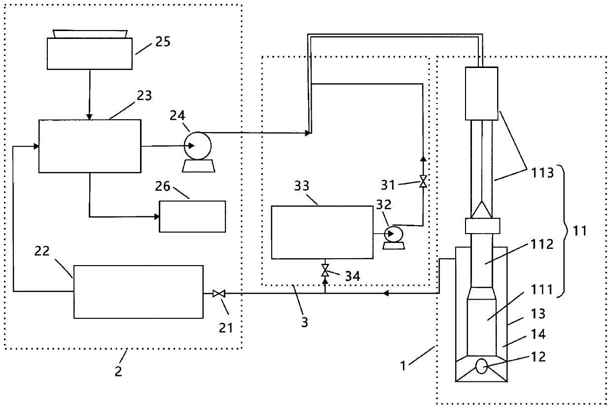
[0025] See figure 1 The embodiment of the present invention provides a drilling fluid circulation system for reducing the suction pressure of drilling and tripping, which includes: a drilling tool assembly 1 , a normal drilling circulation channel 2 and a tripping circulation channel 3 .

[0026] See figure 1 , the drilling tool assembly 1 is used to drill the formation, including a drill string 11 and a drill bit 12, the drill string 11 is hollow with two ends open, and is used to transport drilling fluid from the surface to the bottom of the well, and the drill bit 12 It is fixedly arranged at one end of the drill string 11. The outer sidewall of the drill string 11 and the inner sidewall 13 of the wellbore form an annular space 14, and the annular s...


PUM


Abstract

The invention provides a drilling fluid circulation system for reducing the drilling trip-out suction pressure. The drilling fluid circulation system comprises a drilling rig assembly, a normal drilling circulation channel and a trip-out and trip-in circulation channel. The drilling rig assembly includes a drill string and a drilling bit. The normal drilling circulation channel includes a first rotating valve, a solid phase control device, a mud tank and a mud pump which communicate one another in sequence. The trip-out and trip-in circulation channel includes a second rotating valve, a trip-out and trip-in pump, a trip-out and trip-in mud tank and a third rotating valve which communicate one another in sequence. The method for reducing the drilling trip-out suction pressure through the drilling fluid circulation system includes the steps that before trip out, the first rotating valve and mud pump are closed, the second rotating valve and the third rotating valve are opened, the displacement of the trip-out and trip-in pump is determined according to relevant parameters, and the trip-out and trip-in pump is started to enable the displacement to reach a displacement value of the trip-out and trip-in pump. According to the technical scheme, the drilling fluid circulation system has the beneficial effects that a trip-out and trip-in mud circulation loop is added in a conventional mud circulation loop, and the mud circulation loop is used during trip out and trip in for reducing the trip-out and trip-in suction pressure.

Description

technical field [0001] The embodiments of the present invention relate to the technical field of drilling engineering, in particular to a drilling fluid circulation system for reducing suction pressure during drilling and tripping. Background technique [0002] With the development of oil and gas production in the direction of deep strata and deep water, drilling encounters more and more narrow safe density windows. In the narrow safe density window environment, because the pore pressure of the formation is close to the fracture pressure, the bottom hole pressure caused by the tripping operation of the well Fluctuations make the bottom hole pressure easily exceed the window range, resulting in complex downhole accidents such as overflow and lost circulation. [0003] Bottomhole pressure fluctuations are affected by factors such as tripping speed, well depth, drilling fluid density, drilling fluid viscosity, drilling fluid rheology, and tripping depth. The higher the drillin...

Claims


Application Information

Patent Timeline
Patent Type & Authority Applications(China)
IPC IPC(8): E21B21/12E21B21/10E21B21/06E21B3/02E21B44/00
CPCE21B21/12E21B21/10E21B21/062E21B3/02E21B44/00E21B21/082E21B21/085E21B44/02E21B47/06E21B47/22E21B19/08E21B21/106E21B21/00E21B49/005
Inventor 张菲菲王怡迪王越之王茜李思洋
Owner YANGTZE UNIVERSITY
Why Eureka
Try Eureka