Light guide plate encapsulation member and planar light source device or lighting device using same

A technology for light guide components and sealing components, applied in lighting devices, planar/plate-shaped light guides, electric light sources, etc., can solve problems such as interference fringes and damage to optical properties, and achieve embedding suppression, high smoothness, and sufficient bonding strength Effect

Active Publication Date: 2019-09-27
TOMOEGAWA PAPER CO LTD
View PDF4 Cites 0 Cited by
  • Summary
  • Abstract
  • Description
  • Claims
  • Application Information

AI Technical Summary

Problems solved by technology

However, if the surface on which the aforementioned concave portion is formed is the outermost surface, there is a possibility that the optical characteristics may be impaired due to adhesion of dirt, damage, etc.
Furthermore, in the case of laminating with other layers, there is a problem that a thin air layer is formed in the flat portion (region other than the concave portion) of the surface on which the concave portion is formed, thereby causing interference fringes and the like.

Method used


Image

  • Light guide plate encapsulation member and planar light source device or lighting device using same
  • Light guide plate encapsulation member and planar light source device or lighting device using same
  • Light guide plate encapsulation member and planar light source device or lighting device using same

Examples


Embodiment

[0153] Hereinafter, although this invention is demonstrated based on an Example and a comparative example, this invention is not limited to the content of an Example.

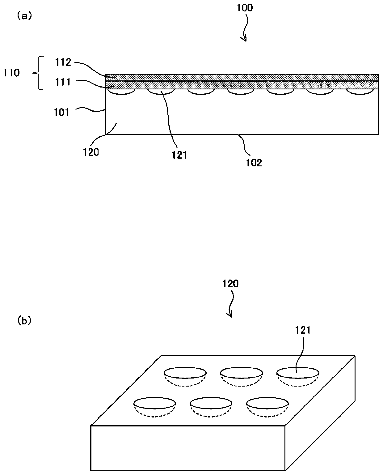
[0154] On a 2mm thick PMMA sheet with a size of 130mm x 90mm, UV curable acrylic resin (containing a photopolymerization initiator) is used to form a coating layer with a thickness of 10 μm, and a convex lens-shaped dot shape with a diameter of about 40 μm and a height of about 10 μm is used. mold (convex lens density: about 100 / mm 2 ) was pressurized while irradiating UV light from the surface of the PMMA sheet on the opposite side to the coating layer to cure, thereby producing a light guide member having a concave portion used in the present invention. The surface of the obtained light guide member was observed with a laser microscope, and it was confirmed that about 100 pieces / mm 2 There is a concave lens-shaped dot-shaped light guide member having a concave portion with a size (diameter) of about 40 μm an...

manufacture example 1

[0156] Synthesis of Compound 1:

[0157] 196.29 g (1 mol) of tricyclodecane dimethanol and 22.828 g (0.2 mol) of ε-caprolactone were added to the flask, the temperature was raised to 120° C., and 50 ppm of monobutyltin oxide was added as a catalyst. Then, the reaction was carried out under nitrogen flow until the remaining ε-caprolactone was less than 1% in gas chromatography to obtain diol (1).

[0158] 444.56 g (2 moles) of isophorone diisocyanate was added to another flask, and 424.57 g (1 mole) of diol (1) was added at a reaction temperature of 70° C., and added when the remaining isocyanate group became 5.7%. 232.24 g (2 moles) of 2-hydroxyethyl acrylate and 0.35 g of dibutyltin laurate were reacted until the remaining isocyanate group was 0.1%, and urethane acrylate (compound 1) was obtained as a monomer.

manufacture example 2

[0160] Except that the amount of ε-caprolactone used was changed from 0.2 mol to 2 mol, the same procedure as in Production Example 1 was carried out to obtain Compound 2 as a monomer (the two ends of Compound 2 are acryloyl groups, except that it is the same as The same applies to the structure in which m is 1 in the general formula (1a).


PUM

PropertyMeasurementUnit
surface roughnessaaaaaaaaaa
peel strengthaaaaaaaaaa
thicknessaaaaaaaaaa

Abstract

To provide: a light guide plate encapsulation member which exhibits sufficient bond strength for bonding to a light guide member with minimized embedding into concavities on the light guide member and which has a highly smooth surface for the part which covers the concavities; a light guide plate using the light guide encapsulation member; and a lighting device or display device using the light guide plate. The light guide plate encapsulation member comprising one or more layers to be laminated on a light guide member that has an emission face wherefrom light entering through an end face is bent and emitted toward the surface and that has multiple concavities disposed on the emission face and / or the opposite face across from the emission face, the one or more layers of the light guide plate encapsulation member being laminated on the face having the concavities so as to encapsulate within the concavities at least one of a gas, a liquid, and a vacuum having a refractive index different from the refractive index of the light guide member. The light guide plate encapsulation member is characterized by having the layer thereof abutting the face with the concavities comprise an encapsulation layer containing a resin which comprises repeat units derived from urethane (meth) acrylate having a saturated cycloaliphatic group.

Description

technical field [0001] The present invention relates to a sealing member for a light guide plate, a planar light source device, or a lighting device used for illumination of image display devices such as LCDs and PDPs, advertisements, display windows, and the like. Background technique [0002] As one form of a light guide plate, it is known to use a plurality of concave lens shapes or dot shapes (hereinafter referred to as concave portions) formed on the surface to reflect and refract light received from an end surface and emit it to the outside. However, if the surface on which the aforementioned concave portion is formed is the outermost surface, there is a possibility that the optical characteristics may be impaired due to adhesion of dirt, damage, and the like. Furthermore, when laminated with another layer, there is a problem that a thin air layer is formed in the flat portion (region other than the concave portion) of the surface on which the concave portion is formed...

Claims


Application Information

Patent Timeline
Patent Type & Authority Applications(China)
IPC IPC(8): G02B6/00G02F1/13357C08F290/06
CPCC08F290/06F21S2/00G02B1/14G02B5/02G02B6/0035C08G18/755C08G18/4277C08G18/672C08G18/73C09D175/16B32B2255/10B32B2307/748B32B2307/7242B32B27/40B32B2250/02B32B27/30B32B2307/412B32B2590/00B32B27/34B32B27/365B32B2255/26B32B27/36B32B27/285B32B2457/202B32B2307/7265B32B2307/538B32B3/30B32B2250/24B32B2457/204B32B27/08B32B27/32C08G18/42C08L33/06G02B6/10C08F220/36C08F220/343C08F290/067G02B6/0036G02B6/0093
Inventor 菅将吾加藤昌央坂野翼杉山仁英
Owner TOMOEGAWA PAPER CO LTD
Why Eureka
Try Eureka