
Cutting tool and manufacturing method thereof

A cutting tool and coating technology, applied in the cutting tool and its manufacturing field, can solve the problems of decreasing coating hardness, limiting coating oxidation resistance and wear resistance, banner decomposition, etc. effect of color

Active Publication Date: 2019-10-11
GANZHOU ACHTECK TOOL TECH
View PDF9 Cites 4 Cited by
  • Summary
  • Abstract
  • Description
  • Claims
  • Application Information

AI Technical Summary

Problems solved by technology

[0008] To sum up, it can be concluded from the prior art that a coating containing Ti, Al, Si, N and other elements can be prepared by doping silicon into fcc-AlTiN by PVD method, but since the Al content cannot exceed 67%, thus limiting the improvement of the coating's oxidation resistance and wear resistance
High-aluminum fcc-AlTiN coatings can be prepared by CVD, but because the coating is a metastable phase structure, it is prone to strip decomposition under long-term high-temperature cutting to form hcp-AlTiN, resulting in a decrease in coating hardness and wear resistance decreased sex

Method used


Image

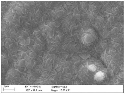
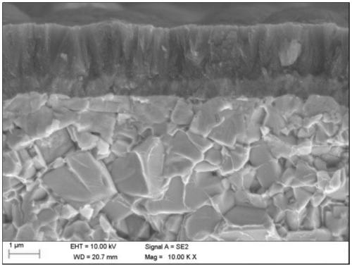
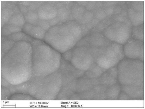
  • Cutting tool and manufacturing method thereof
  • Cutting tool and manufacturing method thereof
  • Cutting tool and manufacturing method thereof

Examples


Embodiment 1

[0051] Manufacturing cutting tools, in this embodiment, cutting tools are indexable inserts, prepared by the following steps:

[0052] A substrate is provided in the reaction site. In this embodiment, the substrate is a cemented carbide indexable insert. The composition of the cemented carbide includes 12% Co, 1.5% cubic carbide and the balance of WC. The model of bit blade is SNGX1206ANN-MM4;

[0053] (1) The first reaction gas is provided in the reaction place containing the cemented carbide indexable insert. In this embodiment, the first reaction gas is SiCl 4 , the silicon source is SiCl 4 , the proportion in the total reaction gas is 0.08%;

[0054] (2) The second reaction gas is provided in the reaction place containing the cemented carbide indexable insert. In this embodiment, the second reaction gas is AlCl 3 , the aluminum source is AlCl 3 , the proportion in the total reaction gas is 0.39%;

[0055] (3) Other reactive gases are provided in the reaction place tha...

Embodiment 2

[0062] In this embodiment, the cutting tool is an indexable insert, which is prepared through the following steps:

[0063] A substrate is provided in the reaction site. In this embodiment, the substrate is a cemented carbide indexable insert. The composition of the cemented carbide includes 8% Co, 1.6% cubic carbide and the balance of WC. The model of bit blade is SNGX1206ANN-MM4;

[0064] (1) The first reaction gas is provided in the reaction place containing the cemented carbide indexable insert. In this embodiment, the first reaction gas is SiCl 4 , the silicon source is SiCl 4 , the proportion in the total reaction gas is 0.18%;

[0065] (2) The second reaction gas is provided in the reaction place containing the cemented carbide indexable insert. In this embodiment, the second reaction gas is AlCl 3 , the aluminum source is AlCl 3 , the proportion in the total reaction gas is 0.39%;

[0066] (3) Other reactive gases are provided in the reaction place that accommodat...


PUM

PropertyMeasurementUnit
thicknessaaaaaaaaaa
particle sizeaaaaaaaaaa
microhardnessaaaaaaaaaa

Abstract

The invention discloses a cutting tool and a manufacturing method thereof. The cutting tool comprises a substrate and a single layer of coating or multiple layers of coatings, the single layer of coating or the multiple layers of coatings coat the substrate, the single layer of coating or the multiple layers of coatings internally at least comprises one layer of (AlxSiyTi1-x-y)N coating, wherein xis greater than or equal to 0.70, y is greater than 0 and less than or equal to 0.1. According to the cutting tool and the manufacturing method thereof, the (AlxSiyTi1-x-y)N coating coats the cuttingtool, high aluminum of the coating is ensured, meanwhile, an amorphous coated nanocrystalline structure is formed due to doping of Si elements, the coating structure is refined, the high-temperaturehardness of the coating is improved, the oxidation resistance of the coating is not reduced, and meanwhile, the wear resistance of the coating is improved.

Description

technical field [0001] The invention belongs to the field of material processing, and in particular relates to a cutting tool and a manufacturing method thereof. Background technique [0002] The modern manufacturing industry is developing in the direction of high efficiency and environmental protection. With the increasing proportion of high-speed and dry cutting, the performance requirements of cutting tools are also getting higher and higher. Today, the performance of traditional carbide cutting tools can no longer adapt to high-speed, dry cutting. Therefore, various technologies for coating cemented carbide tools to improve their cutting performance have been developed one after another. In order to meet the needs of high-speed and dry machining and achieve better performance, the composition of the coating is becoming more and more complex, and the structure of the coating has also developed from a simple single coating to a variety of complex structures. [0003] For...

Claims


Application Information

Patent Timeline
Patent Type & Authority Applications(China)
IPC IPC(8): C23C16/34
CPCC23C16/34C23C28/044
Inventor 谭卓鹏朱骥飞成伟邱联昌殷磊李世祺傅声华陈丽勇
Owner GANZHOU ACHTECK TOOL TECH
Learn More