Pyrolytic carbonization device and method for steel rolling oil sludge treatment

A technology of pyrolysis carbonization and steel rolling oil sludge, which is applied in the fields of pyrolysis treatment of sludge, petroleum industry, by-product vaporization, etc. It can solve the problems of increasing labor intensity and maintenance expenditure, clogging of reaction materials, screw stuck shaft, and smaller reaction space, etc. problems, to achieve the effect of reducing labor intensity and maintenance costs, reducing equipment energy consumption and mechanical wear, and extending the maintenance cycle

Active Publication Date: 2019-10-15
AT&M ENVIRONMENTAL ENG TECH CO LTD +1
View PDF4 Cites 15 Cited by
  • Summary
  • Abstract
  • Description
  • Claims
  • Application Information

AI Technical Summary

Problems solved by technology

[0005] However, in long-term actual production, it is found that steel rolling sludge is generally viscous, especially after long-term storage, the water in the sludge gradually evaporates, the fluidity of the sludge decreases, the viscosity increases, and the power required for feeding increases; at the same time, the organic matter The pyrolysis of pyrolysis is a complex process, which will produce large sticky ash, small particles of dust, etc. within a certain period of time. The tar gas generated during the mixed reaction process will continue to accumulate during long-term operation, making the inner wall of the carbonization tube and The pyrolysis gas burner is gradually blocked, resulting in a smaller reaction space for the material, fouling and dust accumulation at the bottom of the tube wall, and the heat transfer effect of the carbonization tube is also deteriorated, making it difficult to heat up the reaction space, increasing energy consumption, and increasing mechanical wear ( Shaft end bearings are relatively prominent), serious cases may even cause reaction material blockage, screw stuck shaft, etc., lighter ash will enter the waste heat recovery device with the wind and smoke, and adhere to the heat exchanger surface of the waste heat recovery device. The load of the long-term operation unit As the heat transfer and rolling oil sludge treatment effect will become worse, it is necessary to frequently clean the inner wall of the carbonization furnace, bearings, waste heat recovery devices and other easy-to-fouling heating surfaces, which increases the labor intensity and maintenance costs required for maintenance.

Method used


Image

  • Pyrolytic carbonization device and method for steel rolling oil sludge treatment
  • Pyrolytic carbonization device and method for steel rolling oil sludge treatment
  • Pyrolytic carbonization device and method for steel rolling oil sludge treatment

Examples


Embodiment Construction

[0036] In order to enable those skilled in the art to better understand the technical solutions of the present invention, the present invention will be further described in detail below in conjunction with the accompanying drawings.

[0037]It should be noted that in this article, relational terms such as first and second are only used to distinguish one entity or operation from another entity or operation, and do not necessarily require or imply that there is a relationship between these entities or operations. There is no such actual relationship or order between them. Furthermore, the term "comprises", "comprises" or any other variation thereof is intended to cover a non-exclusive inclusion such that a process, method, article, or terminal equipment comprising a set of elements includes not only those elements, but also includes elements not expressly listed. other elements identified, or also include elements inherent in such a process, method, article, or end-equipment. ...


PUM


Abstract

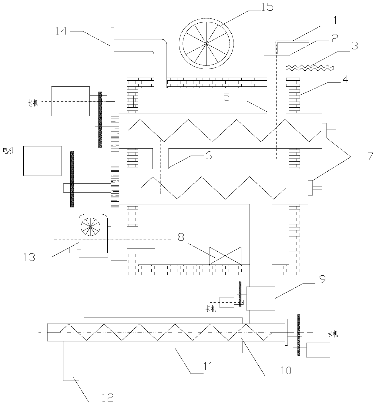
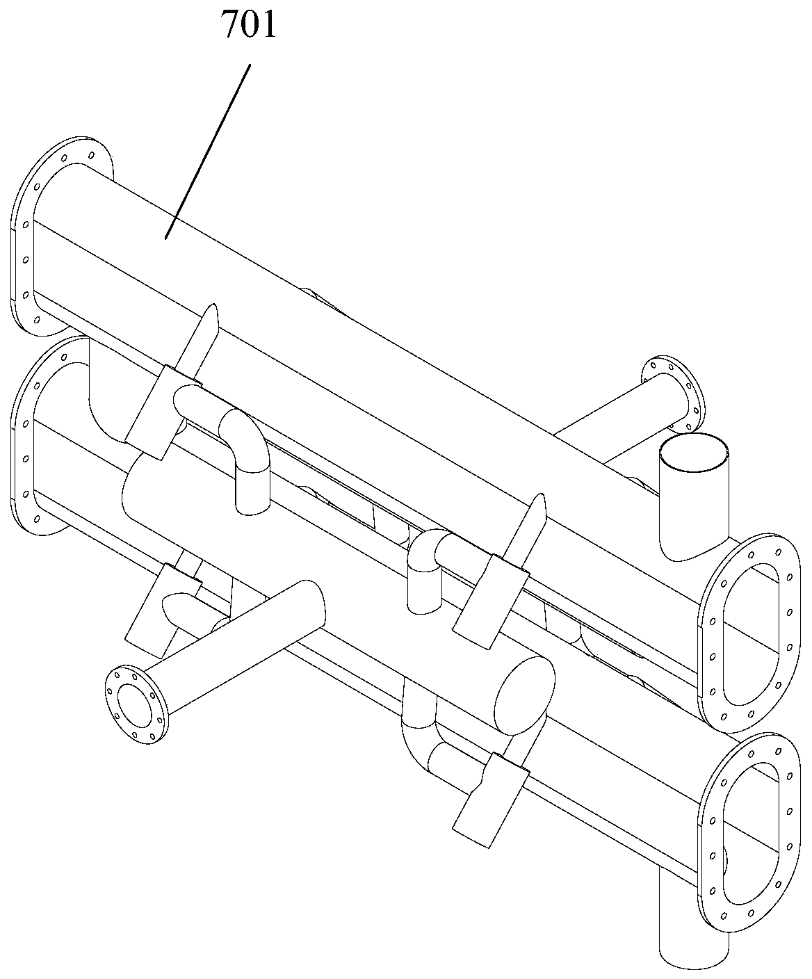
The invention provides a pyrolytic carbonization device and method for steel rolling oil sludge treatment. A steel rolling oil sludge carbonization device is improved on the basis of the patent with publication number CN107963796A and mainly comprises a feeding device, a pyrolytic carbonization device arranged in a casing, a cooling device, a combustible gas treatment device, a temperature detection element, an electrical control system, a waste heat recovery device and a tail gas treatment device. On the basis of scientific and safe treatment of the steel rolling oil sludge and utilization ofheat contained in organic components of the steel rolling oil sludge and 90% or more of a material reduction rate, the pyrolytic carbonization device and method have the advantages that by means of optimization for carbonization main device structures, including structures and number of carbonization pipes, spiral shafts and the like, the cavity area of a carbonization furnace is increased, movement resistance is reduced, and adhesion, scaling and the like caused by mixing of large-particle ash residues and small-particle ash with tar gas in a long-term carbonization process are prevented andrelieved.

Description

technical field [0001] The invention relates to the technical field of pyrolysis sludge treatment, in particular to a pyrolysis carbonization device and method for treating steel rolling sludge. Background technique [0002] The rolling oil and emulsion used for cooling and lubrication in the cold rolling industry will undergo deterioration and separation under long-term high-temperature rolling, and then be separated by the process lubrication and filtration system of the steel rolling equipment to form waste sludge—steel rolling sludge. Once fermented, the original microorganisms in the steel rolling sludge expand in volume and have an odor. Long-term stacking will damage the soil and water bodies, causing great harm to the environment. The Ministry of Environmental Protection has listed it as a hazardous waste, numbered HW08. [0003] At present, small and medium-sized iron and steel enterprises generally use the transfer method to transfer oil sludge to units with hazard...

Claims


Application Information

Patent Timeline
Patent Type & Authority Applications(China)
IPC IPC(8): C02F11/10C10B53/00
CPCC02F11/10C10B53/00Y02P20/129Y02W10/40
Inventor 王跃董凯杨旭焦亮亮王振华
Owner AT&M ENVIRONMENTAL ENG TECH CO LTD
Why Eureka
Try Eureka