
Wide-band oxygen sensor structure

An oxygen sensor, a wide-area technology, applied in the field of oxygen sensors, can solve the problems of shortening the service life of oxygen sensors, loose connection points, unwritten sensor elements and signal lines, etc., to improve assembly and debugging efficiency, avoid looseness, and avoid The effect of corrosion

Pending Publication Date: 2019-10-15
莱鼎电子材料科技有限公司
View PDF9 Cites 2 Cited by
  • Summary
  • Abstract
  • Description
  • Claims
  • Application Information

AI Technical Summary

Problems solved by technology

[0004] First, it is recorded in the literature that the sensor element is fixed in the outer cylinder by pressing the ceramic ring, the upper ceramic ring and the waterproof plug, and there is no fixing between the upper ceramic ring and the waterproof plug. Therefore, in actual use, the oxygen sensor will be in a long-term vibration state along with the automobile exhaust pipe, and the sensing element (recorded as a chip in this document) is not completely fixed, which will cause the sensing element and the signal line to be disconnected during long-term use. The connection point is loose, which shortens the service life of the oxygen sensor;
[0005] Second, there is no written record in this document on how to connect the sensor element to the signal line. According to the drawings in the manual, the sensor element and the wire are directly connected together. At present, the manufacturer of the oxygen sensor will, during production and processing, The signal line is welded to the contact of the sensing element, so the contact welding step is required in the processing technology, but once welded, there will be invalid processes such as disassembly and rework after the problem is found in the follow-up inspection, so a convenient connection is required and separate structures for sensing elements and signal lines

Method used


Image

  • Wide-band oxygen sensor structure
  • Wide-band oxygen sensor structure
  • Wide-band oxygen sensor structure

Examples


Embodiment Construction

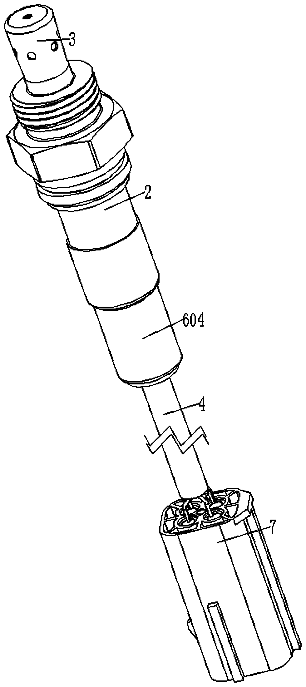
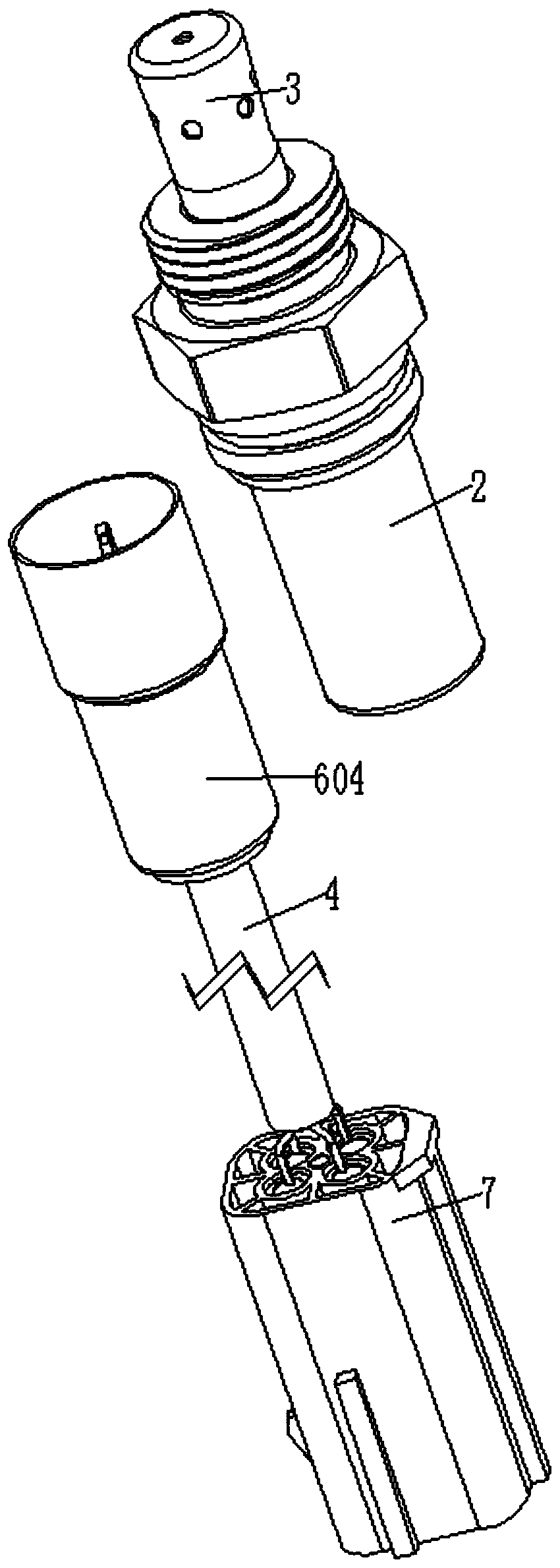
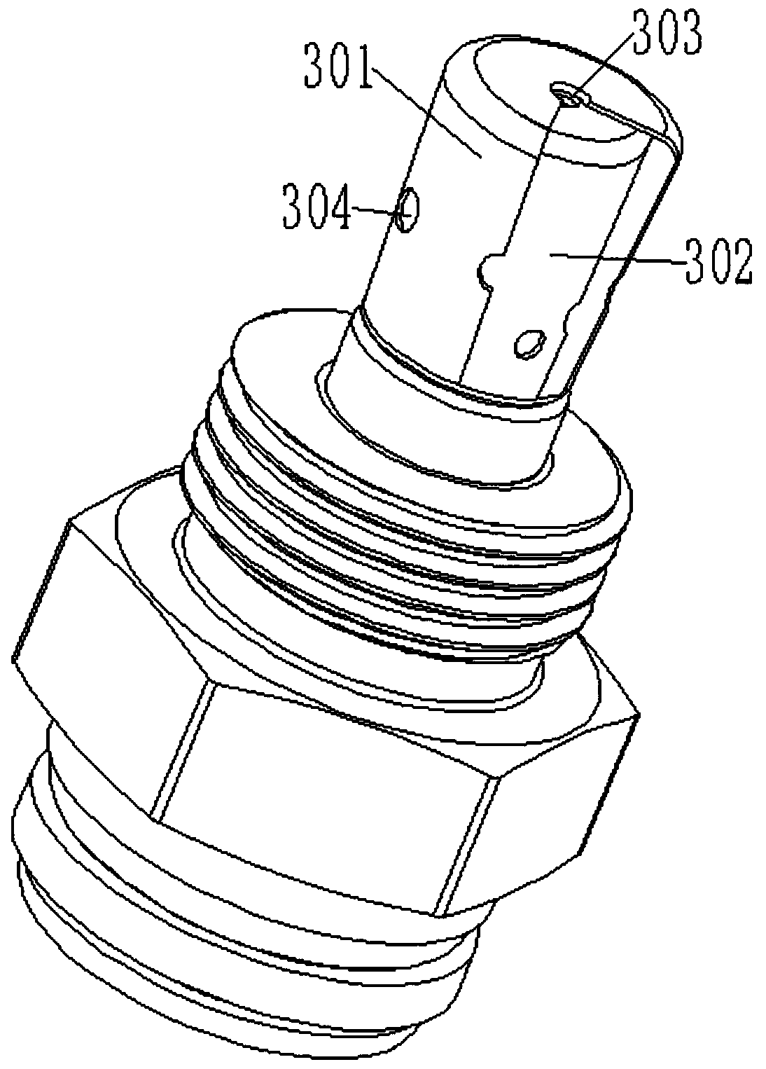
[0031] The present invention will be specifically described below in conjunction with the accompanying drawings, such as Figure 1-12As shown in the figure, the five-wire and five-plug oxygen sensor structure includes a chip 1 for detecting the oxygen ion content in the exhaust gas, a casing 2 for fixedly supporting the chip 1, and arranged at the head of the casing 2 to protect the chip 1 and surround the chip 1. The short shield 3 for sampling the chip 1 from the exhaust gas is arranged on the signal wire 4 connected to the chip 1 through a cable at the tail of the casing 2, and the spring joint 6 between the chip 1 and the signal wire 4 is arranged. The connector 7 at the other end of the signal wire 4, wherein the chip 1 includes a main board 101, a sensing piece 102 arranged at the head of the main board 101, and a contact electrode 103 arranged at the tail of the main board 101, and the sensing piece 102 is used for sensing automobile exhaust gas The oxygen ion content i...


PUM


Abstract

The invention discloses a wide-band oxygen sensor structure. The wide-band oxygen sensor structure comprises a chip, a shell, a short protective cover and a signal conductor, wherein the chip comprises a mainboard, an induction sheet and a contact electrode; a locating seat used for fixing the chip to prevent the chip from shaking in the shell during operation is arranged between the shell and thechip, and all parts, except the induction sheet, of the chip are arranged in the locating seat; and the signal conductor and the chip are connected through an elastic sheet connector, and the elasticsheet connector is inserted into the tail of the locating seat to make contact with the contact electrode and make a signal conducted. The wide-band oxygen sensor has the advantages that talcum powder production rings are arranged between the shell and the chip, the rings are crushed and filled into surrounding space, and then a sealing function can be achieved; and since the signal conductor andthe chip are connected through the elastic sheet connector, the assembling and debugging efficiency of the oxygen sensor in an assembling technological process is improved by changing an existing welding mode into an elastic sheet structure inserting / pulling connection mode.

Description

technical field [0001] The invention relates to the field of oxygen sensors, in particular to a wide-area oxygen sensor structure. Background technique [0002] The oxygen sensor is an important feedback sensor in the engine control system. By detecting the oxygen concentration in the exhaust gas of the automobile, a potential difference is generated on the chip to determine whether the fuel is fully burned, and then the fuel injection amount of the engine is adjusted to make the fuel of the automobile fully burn and reduce the number of automobiles. The emission of exhaust pollutants can reduce the environmental pollution of automobiles and reduce the fuel consumption of automobiles. [0003] After a patent search, it was found that the announcement number: CN208076449U, the announcement date was 20181109, and an automotive oxygen sensor was proposed. There are two deficiencies in the existing solution. [0004] First, it is recorded in the literature that the sensing elem...

Claims


Application Information

Patent Timeline
IPC IPC(8): G01N27/409G01N27/00
CPCG01N27/409G01N27/00
Inventor 黄海琴朱银涛陈圣龙朱卫兵陶建兵韩旭
Owner 莱鼎电子材料科技有限公司
Learn More