Multi-mode eight-frequency high-efficiency high-gain power amplifier

A technology for power amplifiers and power amplification, applied in power amplifiers, radio frequency amplifiers, amplifiers, etc., can solve the problems of bulky amplification systems, difficulty in multi-frequency and multi-mode mutual constraints, low power output capability and power gain capability, etc.

Pending Publication Date: 2019-10-18
TIANJIN CHENGJIAN UNIV +1
View PDF0 Cites 2 Cited by
  • Summary
  • Abstract
  • Description
  • Claims
  • Application Information

AI Technical Summary

Problems solved by technology

However, in the design of traditional high-efficiency power amplifiers, there have always been some design problems, mainly reflected in the difficulty of multi-frequency and multi-mode when compatible with high-efficiency indicators and mutual constraints
In order to ensure the high-efficiency and high-gain operation of the amplifier, the transistor must achieve a good and accurate compromise between the best efficiency and gain matching in the multi-frequency mode, but the realization of the multi-frequency power amplifier has always been the technical bottleneck
[0003] Common high-efficiency, high-gain multi-frequency power amplifier circuit solutions include multiple single-frequency point power amplifiers to form a load amplification system, and each power amplifier achieves the best circuit design at its own frequency point, but this type of amplifi

Method used


Image

  • Multi-mode eight-frequency high-efficiency high-gain power amplifier
  • Multi-mode eight-frequency high-efficiency high-gain power amplifier

Examples


Embodiment Construction

[0014] Below in conjunction with accompanying drawing and specific embodiment the present invention is described in further detail:

[0015] It should be understood that the implementations shown and described in the drawings are only exemplary, intended to explain the principle and spirit of the present invention, rather than limit the scope of the present invention.

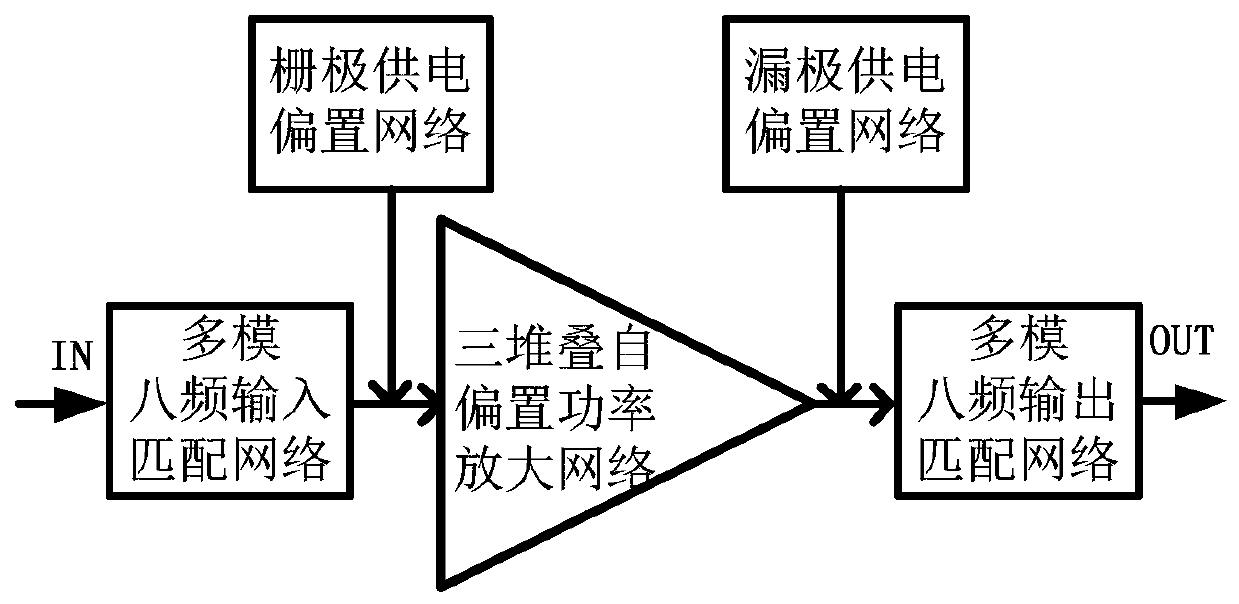
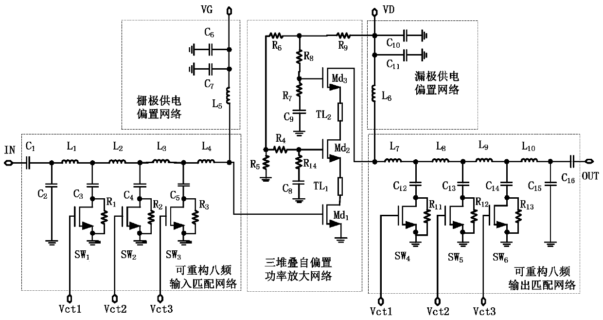
[0016] The implementation of the present invention provides a multi-mode eight-frequency high-efficiency high-gain power amplifier, such as figure 1 As shown, the multi-mode eight-frequency input matching network, the three-stack self-bias power amplifier network, the multi-mode eight-frequency output matching network, the gate supply bias network and the drain supply bias network; the multi-mode eight-frequency input matching network The input end is the input end of the entire multi-mode eight-frequency high-efficiency high-gain power amplifier, and its output end is connected to the input end of the three-st...


PUM


Abstract

The invention discloses a multi-mode eight-frequency high-efficiency high-gain power amplifier which comprises a multi-mode eight-frequency input matching network, a three-stack self-bias power amplification network and a multi-mode eight-frequency output matching network which are connected in sequence. The grid power supply bias network and the drain power supply bias network are respectively connected with the multimode eight-frequency input matching network and the multimode eight-frequency output matching network. The power amplifier has the beneficial effects that a three-stack transistor structure based on a self-bias structure is adopted, and a multimode LC matching network is combined, so that the power amplifier has multimode characteristics of high efficiency, high gain and highpower output capability at eight frequency points.

Description

technical field [0001] The invention relates to the field of a field effect transistor radio frequency power amplifier and an integrated circuit, in particular to a multi-mode, eight-frequency, high-efficiency and high-gain power amplifier for application to a radio frequency front-end transmitting module of a multi-frequency and multi-mode communication system. Background technique [0002] With the development of modern military and civilian communication technologies, RF front-end transmitters are also developing in the direction of multi-frequency, multi-mode, high efficiency, high gain, and high power output. Therefore, the market urgently needs multi-frequency multi-mode, high-efficiency, high-gain, high-power power amplifiers. However, in the design of traditional high-efficiency power amplifiers, there have always been some design problems, mainly reflected in the difficulty of multi-frequency and multi-mode mutual constraints when compatible with high-efficiency ind...

Claims


Application Information

Patent Timeline
IPC IPC(8): H03F1/02H03F1/56H03F3/193H03F3/21H03F3/24H03F3/45
CPCH03F1/0211H03F1/565H03F3/193H03F3/211H03F3/24H03F3/45179H03F2200/451H03F2203/45056H03F2203/45151H03F2203/45154H03F2203/45201
Inventor 朱琳邬海峰林倩庞毅李梅
Owner TIANJIN CHENGJIAN UNIV
Why Eureka
Try Eureka