Micro bubble generation method and micro bubble generator

A micro-bubble and generator technology, applied in the field of water treatment, can solve the problems of high bubble density, low energy consumption, microbial clogging, etc., and achieve the effects of meeting process needs, low operating costs, and space saving

Pending Publication Date: 2019-10-22
湖南亿纳环保科技有限公司
View PDF1 Cites 4 Cited by
  • Summary
  • Abstract
  • Description
  • Claims
  • Application Information

AI Technical Summary

Problems solved by technology

It is difficult for this invention to simultaneously meet the three requirements of uniform micro-bubble particle size, high bubble density and low energy consumption, and the micro-pores of the micro-porous tube are easy to grow microorganisms to form blockage, thus limiting the application of this technology

Method used


Image

  • Micro bubble generation method and micro bubble generator
  • Micro bubble generation method and micro bubble generator
  • Micro bubble generation method and micro bubble generator

Examples


Embodiment 1

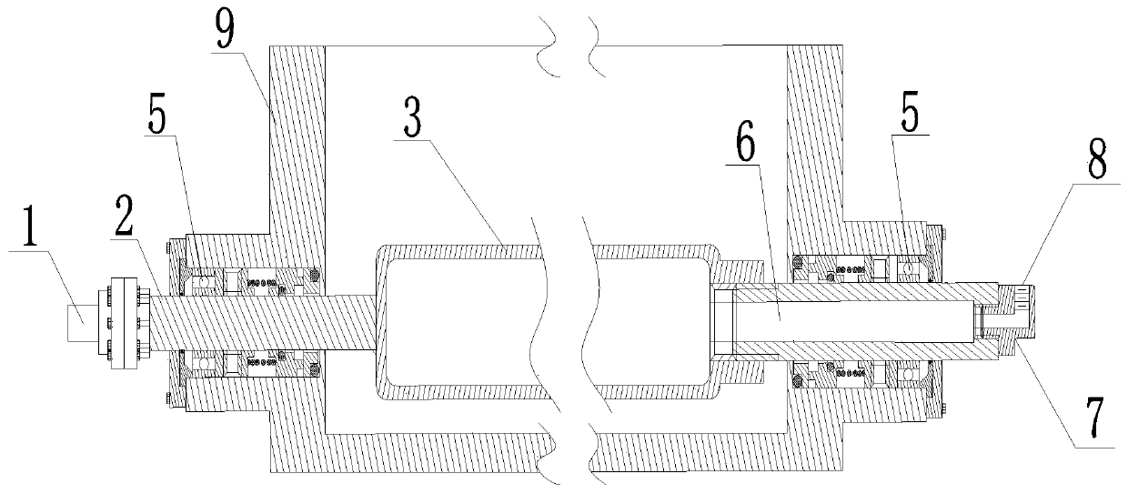
[0035] Such as figure 1 as well as Figure 5 As shown, the microbubble generator provided by the present invention includes a transmission shaft 2, a rotary joint 7, a sealing device, and a cylindrical microporous tube 3 that communicates with the rotary joint 7 and has one end closed. In this embodiment, the transmission shaft 2 is a solid shaft, and the transmission shaft 2 is connected to the sealing end of the microporous tube 3 by means of clamps, threads or welding. One end of the shaft 6 is connected, the other end of the hollow shaft is connected with the rotary end of the rotary joint 7 in the form of a thread opening, and the fixed end of the rotary joint 7 is connected with the air pump. Transmission shaft 2 is installed horizontally. The power comes from the motor 12, and the motor 12 is fixed on the casing 9. The power output shaft 1 of the motor 12 is connected with the solid transmission shaft 2 through a coupling, and the other end of the transmission shaft ...

Embodiment 2

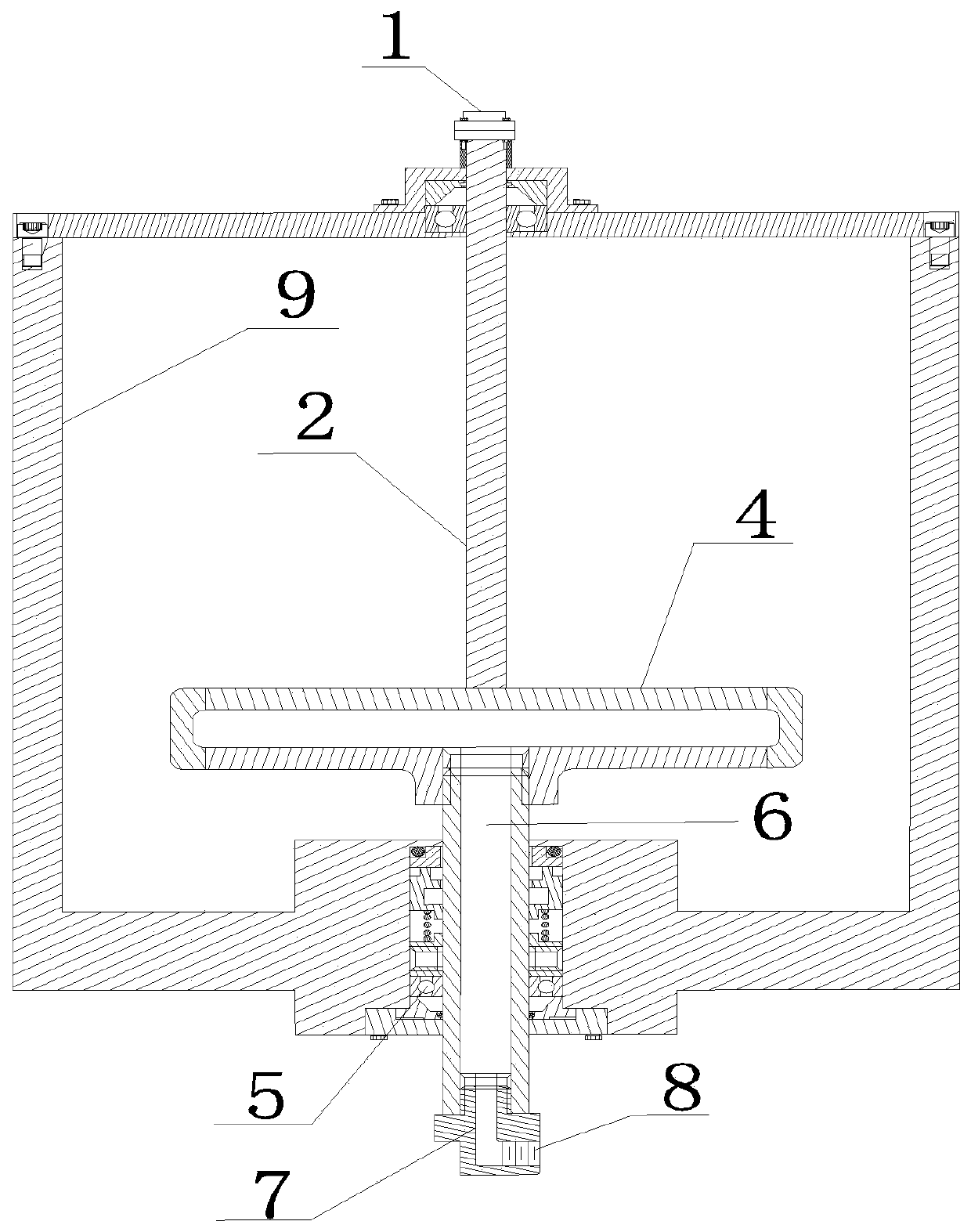
[0037] Such as figure 2 As shown, the microbubble generator provided by the present invention mainly includes a transmission shaft 2, a rotary joint 7, a sealing device, and a disk-shaped microporous disk 4 that is connected to the rotary joint 7 and has one end closed. In this embodiment, the transmission shaft 2 is a solid shaft, and the transmission shaft 2 is connected to the sealing end of the microporous disc 4 by means of clamps, threads or welding. The pipe 6 is connected, and the other end of the hollow pipe 6 is connected with the rotary joint 7 through threads, and the fixed end of the rotary joint 7 is connected with the air pump. Transmission shaft 2 is installed vertically. The power comes from the motor 12, and the motor 12 is fixed on the casing 9. The power output shaft 1 of the motor 12 is connected with the solid transmission shaft 2 through a coupling, and the other end of the transmission shaft 2 is connected with the closed end of the micro-hole disc 4...

Embodiment 3

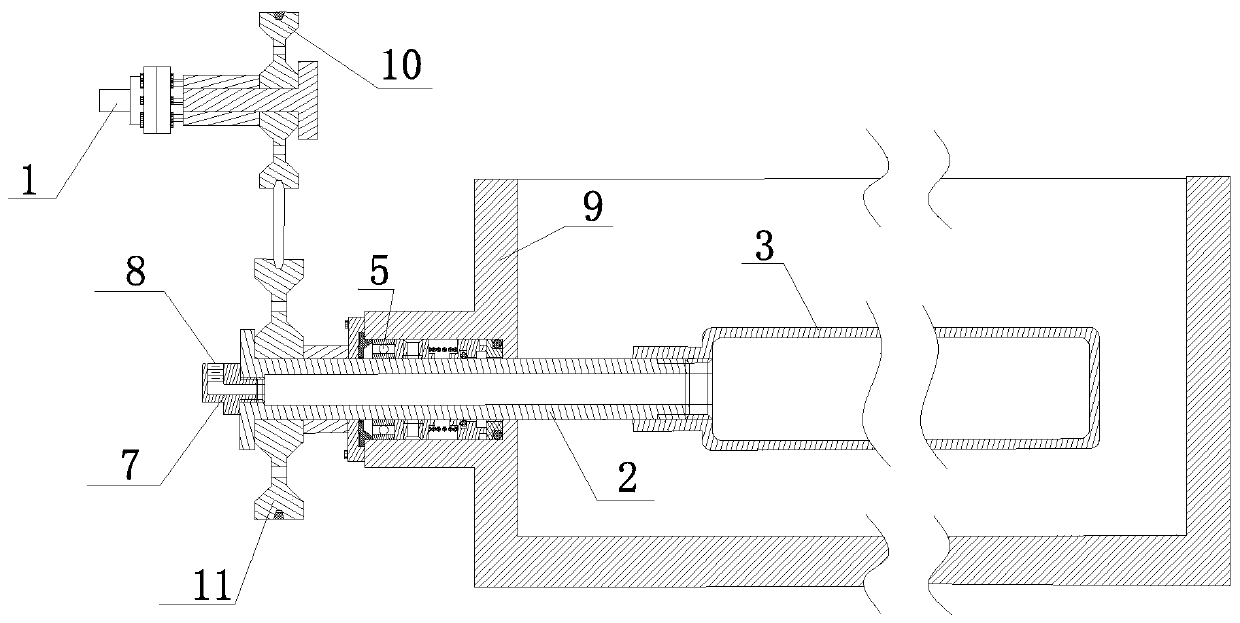
[0039] Such as image 3 As shown, the microbubble generator provided by the present invention mainly includes a transmission shaft 2, a rotary joint 7, a sealing device, and a cylindrical microporous tube 3 that communicates with the hollow tube 6 and has one end closed. In this embodiment, the transmission shaft 2 is a hollow shaft, and the part where the hollow shaft passes through the box body 9 adopts a mechanical seal; the power output shaft 1 drives the transmission shaft 2 through the coupling, the driving wheel 10 and the driven wheel 11 in turn; the transmission shaft 2 is in the One end in the casing is connected with the opening end of the microporous tube 3, and one end of the transmission shaft 2 outside the casing is connected with the rotating end of the rotary joint 7, and the fixed end of the rotary joint 7 is connected with compressed air; in order to make the microporous tube 3 The rotation of the drive shaft is more stable, and the transmission shaft 2 can ...


PUM

PropertyMeasurementUnit
porosityaaaaaaaaaa

Abstract

The invention belongs to the technical field of water treatment and relates to a micro bubble generation method and a micro bubble generator. The micro bubble generator comprises a microporous device,a hollow pipe, a rotating joint, a motor, a power output shaft, a driving shaft and an air pump, wherein the motor is connected with the microporous device through the power output shaft and the driving shaft in sequence and drives the microporous device to rotate around the axial direction of the driving device; the air pump is communicated with the microporous device through the rotating jointand the hollow pipe in sequence and inputs gases into the microporous device; the surface of the microporous device is provided with micropores of which the porosity is not lower than 28 percent; thesize of the micropores is 0.01 to 2 mu m; the gases entering the microporous device overflow from the micropores on the surface of the microporous device to form bubbles with particle size of 5 to 100mu m. The invention provides the micro bubble generation method and the micro bubble generator, which have the advantages of low energy consumption, simple structure and capability of stably producing a large amount of high-density micro bubbles with uniform particle size in liquid phase for a long term.

Description

technical field [0001] The invention belongs to the technical field of water treatment, and relates to a bubble generating device, in particular to a micro bubble generating method and a micro bubble generator. Background technique [0002] Fine bubbles refer to bubbles with a particle size of 1-200um formed by dispersing gas in liquid through physical and chemical methods. Micro-bubbles are used in sewage treatment, sludge concentration, mineral processing, black and odorous water treatment, health care and other fields. The methods of generation include pressurized dissolved air method, multiphase dissolved air pump method and induction method. [0003] The basic principle of the pressurized gas-dissolving method is: firstly, the air or other gas is dissolved in the raw water to be treated under a certain pressure, and reaches a supersaturated state, and then the pressure of the dissolved gas water is reduced to form the gas dissolved in it. Fine air bubbles. This method...

Claims


Application Information

Patent Timeline
Patent Type & Authority Applications(China)
IPC IPC(8): B01F3/04B01F7/26B01F27/93
CPCB01F23/2312B01F23/235B01F27/93B01F2101/48
Inventor 肖灿曹尉南
Owner 湖南亿纳环保科技有限公司
Why Eureka
Try Eureka