

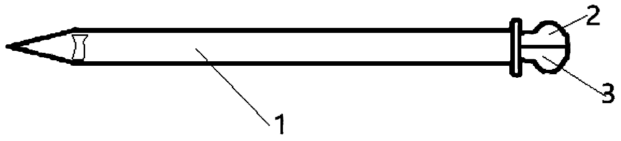
Lumbar cistern drainage tube stealthy indwelling guide device
A technology of guiding device and drainage tube, applied in the field of medical devices, can solve the problems of short maintenance time, loose drainage tube, affecting treatment effect, etc., and achieve the effects of being easy to manufacture, not easily damaged and broken, and easy to popularize and apply.
- Summary
- Abstract
- Description
- Claims
- Application Information
AI Technical Summary
Problems solved by technology
Method used
Image

Examples
Embodiment Construction
[0055] It should be noted that the following detailed description is exemplary and intended to provide further explanation of the present invention. Unless defined otherwise, all technical and scientific terms used herein have the same meaning as commonly understood by one of ordinary skill in the art to which this invention belongs.
[0056] It should be noted that the terminology used here is only for describing specific embodiments, and is not intended to limit exemplary embodiments according to the present invention. As used herein, unless the context clearly dictates otherwise, the singular is intended to include the plural, and it should also be understood that when the terms "comprising" and / or "comprising" are used in this specification, they mean There are features, steps, operations, means, components and / or combinations thereof.
[0057] As introduced in the background technology, there are deficiencies in the prior art. In order to solve the above technical proble...
PUM
 Abstract
Description
Claims
Application Information