
Quick mechanical optical switch with dual voice coil linear motors

A linear motor and double voice coil technology, applied in the laser field, can solve the problems of unbearable high-power laser, vibration noise, slow switching speed, etc., and achieve the effect of simple structure, low vibration noise and strong applicability

Pending Publication Date: 2019-10-25
XI'AN INST OF OPTICS & FINE MECHANICS - CHINESE ACAD OF SCI
View PDF0 Cites 1 Cited by
  • Summary
  • Abstract
  • Description
  • Claims
  • Application Information

AI Technical Summary

Problems solved by technology

[0004] In order to solve the technical problems that the switching speed of the existing mechanical optical switch is relatively slow, or that although the switching speed is fast, there is obvious vibration noise when performing the switching action, and the technical problem that it cannot withstand high-power laser, the present invention proposes a dual-voice coil linear motor fast mechanical optical switch

Method used


Image

  • Quick mechanical optical switch with dual voice coil linear motors
  • Quick mechanical optical switch with dual voice coil linear motors
  • Quick mechanical optical switch with dual voice coil linear motors

Examples


Embodiment 1

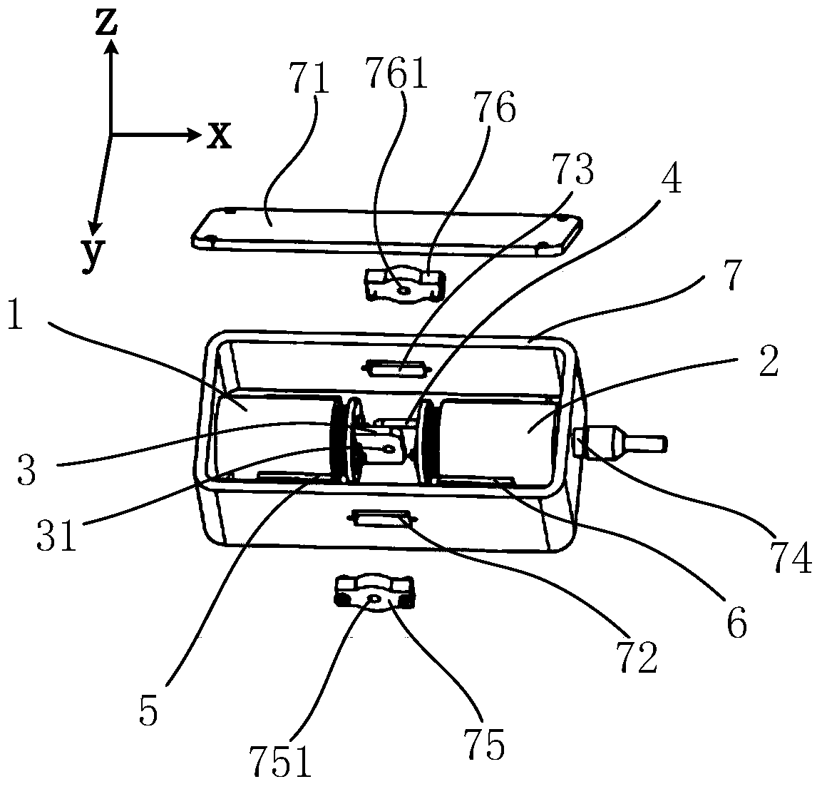
[0044] Such as figure 1 As shown, this embodiment includes a first voice coil linear motor 1, a second voice coil linear motor 2 and a housing 7; the first voice coil linear motor 1 and the second voice coil linear motor 2 are colinearly arranged on the housing along the X direction In the body 7, and the movers of the two are facing oppositely (that is, the direction of motion is opposite);

[0045] The stators of the first voice coil linear motor 1 and the second voice coil linear motor 2 are fixedly connected to the housing 7 through the first fixed structure 5 and the second fixed structure 6 respectively, and the installation distance between the two voice coil linear motors is approximately The maximum stroke of the mover is greater than that of a single voice coil linear motor;

[0046] The mover ends of the first voice coil linear motor 1 and the second voice coil linear motor 2 are respectively connected with a first light blocking plate 3 and a second light blocking...

Embodiment 2

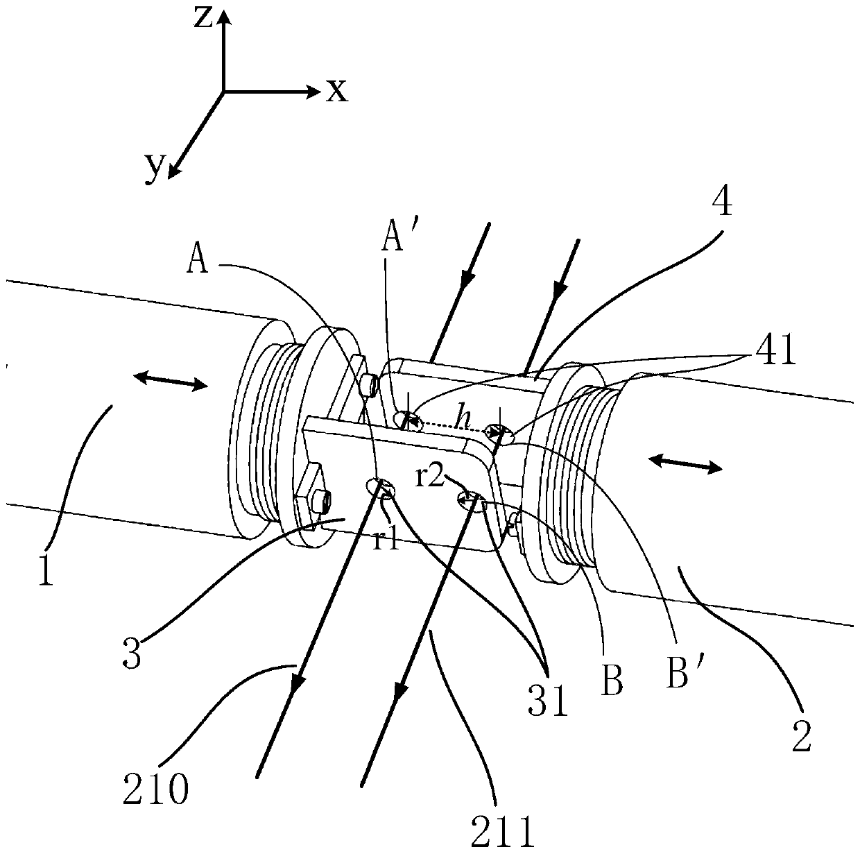
[0060] This embodiment is a scheme for simultaneously realizing switching (that is, N=2) for two laser beams, and the cooperation relationship of the main components is as follows: figure 2 shown. The difference from Embodiment 1 is that two spaced first light holes 31 are provided on the first light blocking plate 3, and two spaced second light holes 41 are set on the second light blocking plate 4. Two third light holes 751 are set on a light plate 75, and two fourth light holes 761 are set on the second light plate 76; the sizes of the two first light holes 31 are respectively the same as the two second light holes 41 are equal, the size of the two third light through holes 751 and the two fourth light through holes is respectively greater than the size of the two first light through holes 31 and the two second light through holes 41; and, the two first light through holes The position of the light through hole 31 satisfies h>r1+r2; the projections of all the first light t...

Embodiment 3

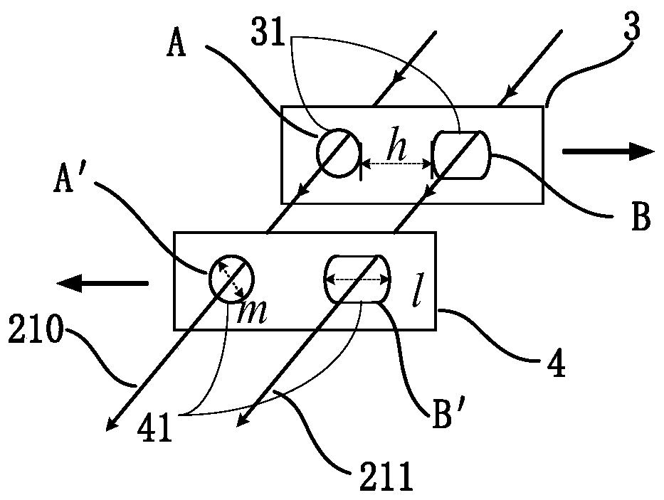
[0066] This embodiment is a scheme for realizing different switching (i.e. N=2) to two laser beams, and the cooperation relationship of the main components is as follows: image 3 As shown (only the light baffle is shown in the figure, the rest are not shown). The difference from Embodiment 2 is that two first light holes 31 with different shapes and sizes are provided on the first light baffle plate 3 at intervals, respectively marked as light hole A and light hole B, and on the second light baffle plate 4, there are two second light holes 41 set at intervals and with different shapes and sizes, which are respectively recorded as light holes A' and light holes B'; the shapes and sizes of light holes A' and light holes B' are the same as The light hole A and the light hole B are respectively the same; the transverse (X direction) dimension of the light hole A is m, the transverse dimension of the light hole B is l, and l>m, the light hole A and the light hole B The horizontal...


PUM


Abstract

The invention provides a quick mechanical optical switch with dual voice coil linear motors, thereby solving problems that the existing mechanical optical switch has the slow switching speed or the existing mechanical optical switch has the fast switching speed but the obvious vibration noises and thus can not carry the large-power laser. The switch comprises a housing, a driving circuit, a firstvoice coil linear motor, and a second voice coil linear motor. The first voice coil linear motor and the second voice coil linear motor are arranged in the housing in parallel or a collinear manner; and moves have opposite directions. A first light blocking plate and a second light blocking plate are arranged at the mover end portions of the first voice coil linear motor and the second voice coillinear motor respectively. M first light transmission holes distributed at intervals are formed in the first light blocking plate and M second light transmission holes distributed at intervals are formed in the second light blocking plate. M third light transmission holes and M fourth light transmission holes are formed in the two opposite side walls of the housing. When the optical switch is in an on state, the M first light transmission holes, the M second light transmission holes, the M third light transmission holes and the M fourth light transmission holes correspond to each other one byone in a concentric manner in a laser beam transmission direction. The M is larger than or equal to 2.

Description

technical field [0001] The invention relates to the field of laser technology, in particular to a double-voice-coil linear motor fast mechanical optical switch. Background technique [0002] Many experiments in laser optics require fast switching of laser beams using Optical Switches (OS). Optical switches are classified according to their structure and technology, and are mainly divided into mechanical optical switches and non-mechanical optical switches. Practical non-mechanical optical switches mostly use acousto-optic modulation (AOM) and electro-optic modulation (EOM) technologies, and their outstanding advantages are fast response speed. The switching time can reach sub-milliseconds or even tens of microseconds, but the beam aperture of this type of switch is small, in most cases the aperture is about 1 mm, and it needs to be carefully aligned when using it. The biggest disadvantage is that the beam cannot be completely turned off. This can be a fatal flaw in some tes...

Claims


Application Information

Patent Timeline
Patent Type & Authority Applications(China)
IPC IPC(8): G02B26/00
CPCG02B26/00
Inventor 贾森王先华蔡勇
Owner XI'AN INST OF OPTICS & FINE MECHANICS - CHINESE ACAD OF SCI
Learn More