A control method for reducing overflow protection time in hydraulic system

A technology of hydraulic system and control method, which is applied in the directions of fluid pressure actuating system components, fluid pressure actuating devices, servo motors, etc. Efficiency, reduction of useless power and heat generation, effect of lowering oil temperature

Active Publication Date: 2020-09-04
深圳东风汽车有限公司
View PDF17 Cites 0 Cited by
  • Summary
  • Abstract
  • Description
  • Claims
  • Application Information

AI Technical Summary

Problems solved by technology

[0011] The technical problem to be solved by the present invention is to provide a control method for reducing the overflow protection time of the hydraulic system, which overcomes the hydraulic system in the prior art, the situation that the light load high pressure overflow time is long, and the heavy load movement is not in place

Method used


Image

  • A control method for reducing overflow protection time in hydraulic system
  • A control method for reducing overflow protection time in hydraulic system
  • A control method for reducing overflow protection time in hydraulic system

Examples


Embodiment 1

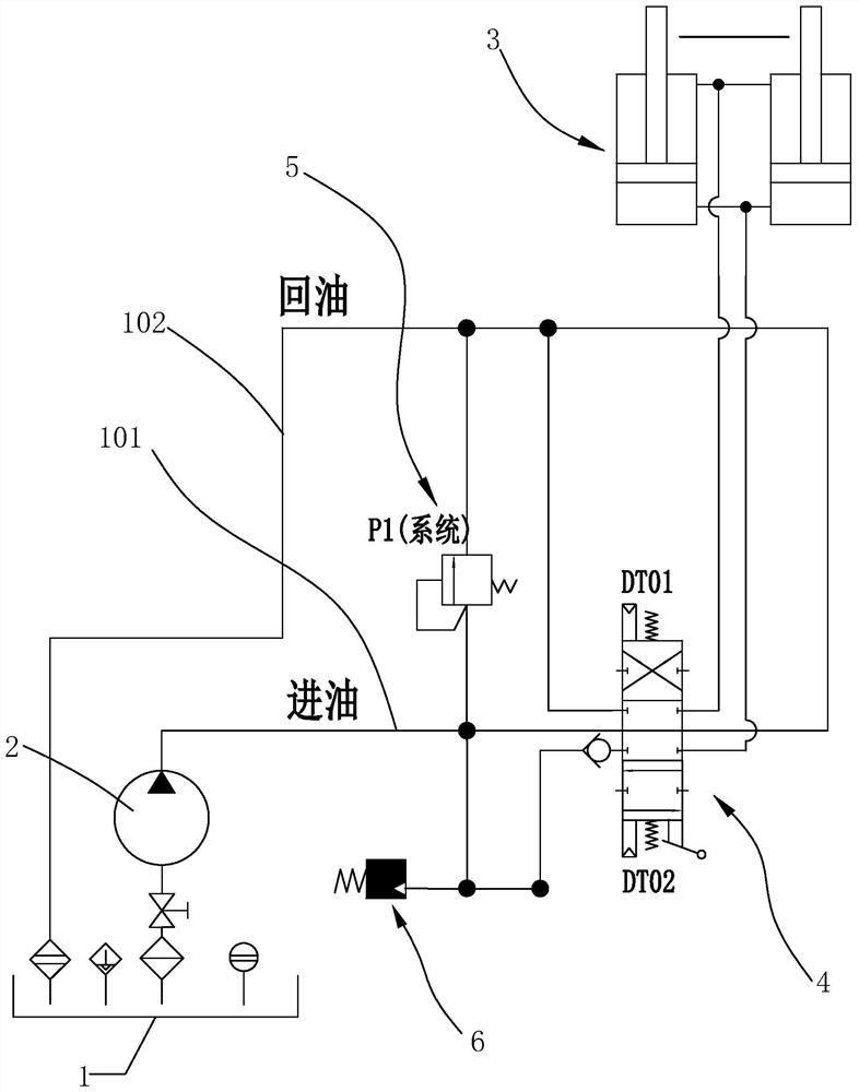
[0056] Such as figure 1 As shown, a control method for reducing the overflow protection time of a hydraulic system in this embodiment, the hydraulic system includes a fuel tank 1, a hydraulic pump 2 connected to the fuel tank 1, and a main oil inlet circuit connected to the hydraulic pump 2 101. The main oil return circuit 102 connected to the oil tank 1, the operating oil cylinder 3, the solenoid valve 4 for controlling the reversing of the operating oil cylinder 3, and the PLC electronic control unit. The operating oil cylinder 3 is connected to the main oil inlet circuit through the electromagnetic valve 4 101 and the main oil return circuit 102, the solenoid valve 4 includes an electromagnet DT01 for controlling the extension of the piston rod of the operating cylinder 3 and an electromagnet DT02 for controlling the retraction of the piston rod of the operating cylinder 3, so The above-mentioned main oil inlet circuit 101 and the main oil return circuit 102 are connected ...

Embodiment 2

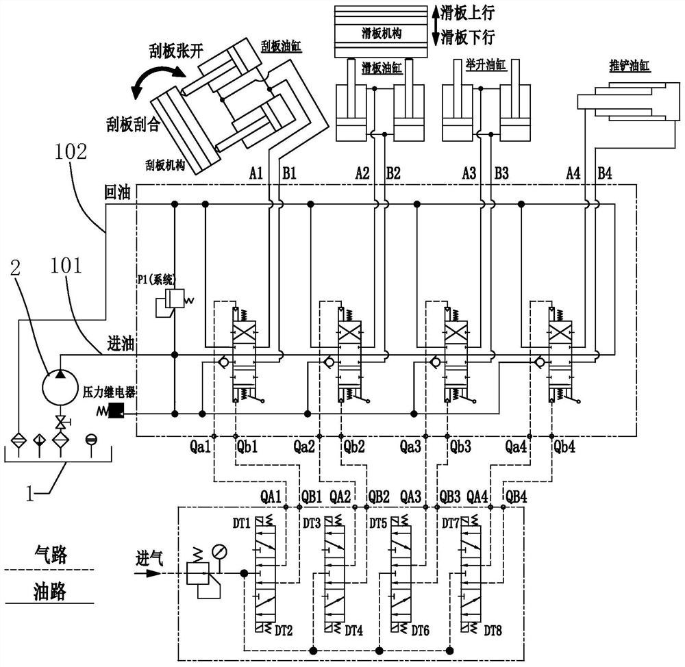
[0070] Such as Figure 2 to Figure 6 As shown, the hydraulic system control method of the compression mechanism of the rear-mounted compression garbage truck of this embodiment, the hydraulic system of the compression mechanism of the rear-mounted compression garbage truck includes a fuel tank 1, a hydraulic pump 2 connected to the fuel tank 1, The main oil inlet circuit 101 connected to the hydraulic pump 2, the main oil return circuit 102 connected to the oil tank 1, the scraper cylinder 31 to control the opening or closing of the scraper, the slider cylinder 32 to control the upward or downward movement of the slider, and the scraper cylinder to control 31 reversing solenoid valve A41, solenoid valve B42 controlling the reversing of the slide cylinder 32, and PLC electronic control unit, the scraper cylinder 31 is connected between the main oil inlet circuit 101 and the main return oil circuit 102 through the solenoid valve A41 During the period, the solenoid valve A41 incl...


PUM


Abstract

The invention discloses a control method for reducing the overflow protection time of a hydraulic system. In a working stroke of a hydraulic cylinder, when the system pressure value is greater than the set value P2, the PLC electric control unit calculates the instantaneous time of the system pressure value Pt Change rate Kt, when the instantaneous change rate Kt is less than the set value A0, that is, the system pressure rises slowly, it is determined that the hydraulic cylinder moves to the maximum stroke position, and the PLC electronic control unit issues an instruction to de-energize the corresponding electromagnet and stop the power supply. Oil, using this control method, no matter how the load changes, it can always make the piston rod move in place, and at the same time reduce the high pressure overflow time, reduce useless power and heat, improve the efficiency of the hydraulic system, reduce the oil temperature, reduce the operating cycle time, and improve the operating efficiency. Beats, improve work efficiency.

Description

【Technical field】 [0001] The invention relates to a control method for reducing overflow protection time of a hydraulic system, and also relates to a control method of a hydraulic system of a compression mechanism of a rear-mounted compression garbage truck. 【Background technique】 [0002] As a very important actuator in the hydraulic system, the hydraulic cylinder is widely used. For the hydraulic system only, the control of the hydraulic cylinder "start-stop-reverse-retract-stop" directly affects the efficiency of the hydraulic cylinder action. The time of the direction directly affects the high-pressure overflow (high-pressure overflow refers to the phenomenon that the piston rod of the hydraulic cylinder moves to the limit position, continues to supply oil, and does not change direction. Due to the protection mechanism of the hydraulic system, the high-pressure oil overflows through the overflow valve) Time, the longer the high-pressure overflow time, the greater the cal...

Claims


Application Information

Patent Timeline
Patent Type & Authority Patents(China)
IPC IPC(8): F15B11/20F15B21/08
CPCF15B11/20F15B21/087
Inventor 李伟涛王富虎姚华军尹声涛李涛
Owner 深圳东风汽车有限公司
Why Eureka
Try Eureka