Novel laser polarization phase shift interference tomography measuring device and method

A phase-shift interference and measurement device technology, applied in the field of measurement, can solve the problems of increasing adjustment difficulty, the phase modulation range cannot be very large, and the optical path structure is complex, and achieves high phase detection accuracy, good anti-interference ability, and elimination of leakage factors. the effect of

Inactive Publication Date: 2019-11-05
NORTH CHINA UNIVERSITY OF TECHNOLOGY
View PDF5 Cites 5 Cited by
  • Summary
  • Abstract
  • Description
  • Claims
  • Application Information

AI Technical Summary

Problems solved by technology

However, the former is affected by the thickness of the compensation plate, and its phase modulation range cannot be

Method used


Image

  • Novel laser polarization phase shift interference tomography measuring device and method

Examples


Embodiment 1

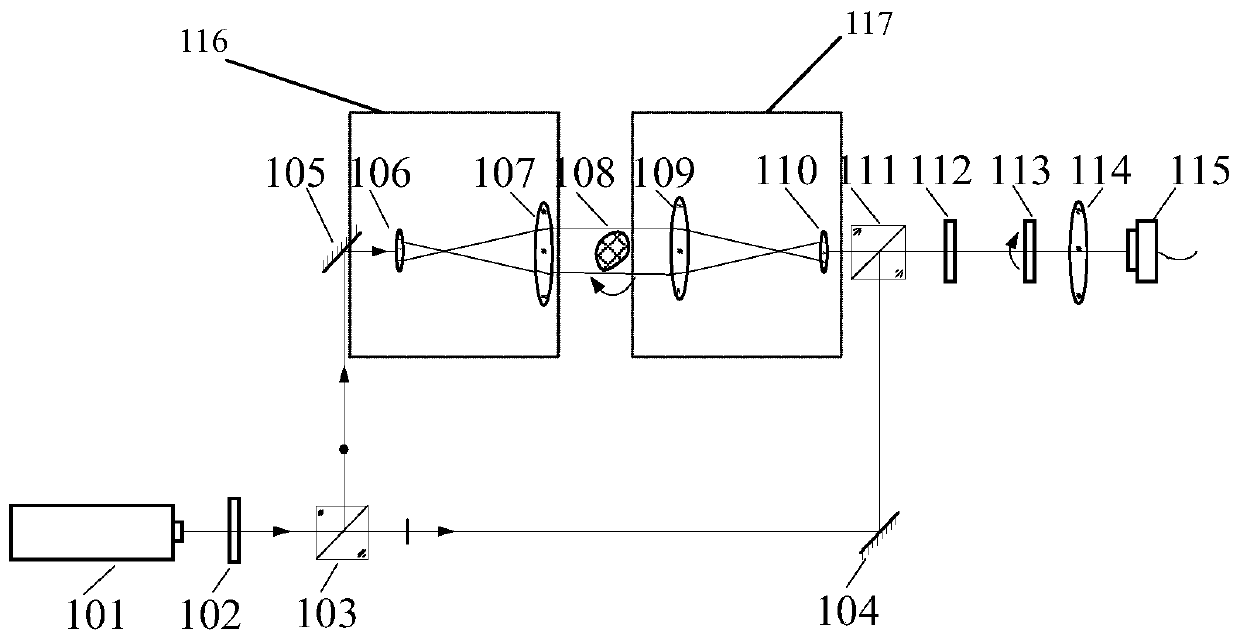
[0031] refer to figure 1 , the preferred embodiment 1 of the present invention provides a novel laser polarization phase-shift interference tomography measurement device, which includes the following components:

[0032] Laser 101: a common commercial He-Ne laser with an output wavelength of 633nm and a beam diameter of about Ф4mm;

[0033] The first polarizer 102 and the second polarizer 113: select a general-purpose high-precision commercial polarizer with a polarization extinction ratio greater than 100:1;

[0034] The first optical lens 106 , the second optical lens 107 , the third optical lens 109 , and the fourth optical lens 110 are high-precision devices commonly used in the market, and the beam expansion and beam reduction ratios are 10 times after assembly.

[0035] Sample 108 to be tested: an irregularly shaped crystal with a size of less than 30×30×30 mm is used. In order to reduce the light deflection caused by the light beam passing through the crystal, the crys...

Embodiment 2

[0040] refer to figure 1, the preferred embodiment 2 of the present invention provides a kind of novel laser polarization phase-shift interference tomography measurement method based on the device described in embodiment 1, which comprises the following steps:

[0041] Step 1: Turn on the laser 101, so that the laser 101 emits a pair of mutually orthogonal linearly polarized lights, that is, a beam of light contains a P-polarized component parallel to the paper surface and an S-polarized component perpendicular to the paper surface;

[0042] Step 2: The light reflected by the polarizing beam splitter 103 and transmitted through the sample to be measured is the measurement light, the light transmitted through the polarizing beam splitter 103 and not passed through the sample to be measured is the reference light, and the measuring light and the reference light are placed between the CCD detector 115 An interference pattern is formed on the image plane;

[0043] Step 3: Rotate ...


PUM

PropertyMeasurementUnit
Beam diameteraaaaaaaaaa

Abstract

The invention relates to a novel laser polarization phase shift interference tomography measuring device. The device comprises a laser, the output optical path of the laser is provided with a first polarizing plate and a polarization beam splitter in order from left to right; the transmission beam path of the polarization beam splitter is provided with a first mirror, and a second mirror is disposed on the reflected light path of the polarization beam splitter; a beam expander system, a sample to be tested and a beam reduction system are sequentially disposed on the reflected light path of thepolarization beam splitter in order from left to right; a beam splitter is disposed at the intersection of the emergent light path of the beam reduction system and the reflected light path of the first mirror, and the transmission beam path of the polarization beam splitter is provided with a quarter wave plate, a second polarizing plate, a focusing lens and a CCD detector in order from left to right. The novel laser polarization phase shift interference tomography measuring device and method provided by the invention are used for measuring the refractive index distribution of a transparent/translucent medium or a flow field, and the phase detection accuracy is higher than that of a conventional optical coherence tomography light path.

Description

technical field [0001] The invention relates to the field of measurement technology, in particular to a novel laser polarization phase-shift interference tomography measurement device and method. Background technique [0002] Optical coherence tomography is a kind of Optical Computed Tomography (OCT), a three-dimensional tomography technology proposed by Fujimoto's research group in 1991 and gradually developed. Based on the principle of interference, it can obtain tomographic capabilities in the depth direction, and can reconstruct the refractive index distribution of the internal structure of the measured sample through multi-projection angle imaging, and then obtain two-dimensional or three-dimensional images. Optical coherence tomography has the characteristics of non-invasive, non-invasive and high-resolution, and has broad application prospects in medical biological detection, flow field detection and transparent medium detection. [0003] The basic principle of optic...

Claims


Application Information

Patent Timeline
IPC IPC(8): G01B9/02
CPCG01B9/0201
Inventor 陈强华孔祥悦孙启国吕洪波何广平司丽娜豆照良祖岩朱炜杨延竹李艳红柴娟芳
Owner NORTH CHINA UNIVERSITY OF TECHNOLOGY
Why Eureka
Try Eureka