
HJT battery and preparation method thereof

A battery and electrode technology, which is applied in the field of solar cells, can solve the problems of heterojunction cell open voltage and fill factor drop, limit the effective use of long-wavelength solar energy, and single-layer ITO thin films cannot meet the needs, etc., to achieve good conductivity , low light absorption, and the effect of reducing the hole barrier

Inactive Publication Date: 2019-11-05
HUNAN RED SUN PHOTOELECTRICITY SCI & TECH
View PDF6 Cites 5 Cited by
  • Summary
  • Abstract
  • Description
  • Claims
  • Application Information

AI Technical Summary

Problems solved by technology

[0005] At present, the TCO film widely used in HJT cells is single-layer ITO, which has good conductivity, but there are the following problems: (1) The high infrared reflectivity limits the effective use of long-wavelength sunlight energy; ( 2) ITO has low carrier mobility, high light absorption, and low transmittance, resulting in low short-circuit current of HJT batteries; (3) ITO does not match the work function of the P-type doped amorphous silicon layer, and the internal The building potential difference decreases, which reduces the opening voltage and fill factor of the heterojunction battery, resulting in a decrease in the performance of the battery
Obviously, a single-layer ITO film cannot meet the demand
In addition, other TCO membranes, such as IMO still have the disadvantage of low conductivity

Method used


Image

  • HJT battery and preparation method thereof
  • HJT battery and preparation method thereof

Examples


Embodiment 1

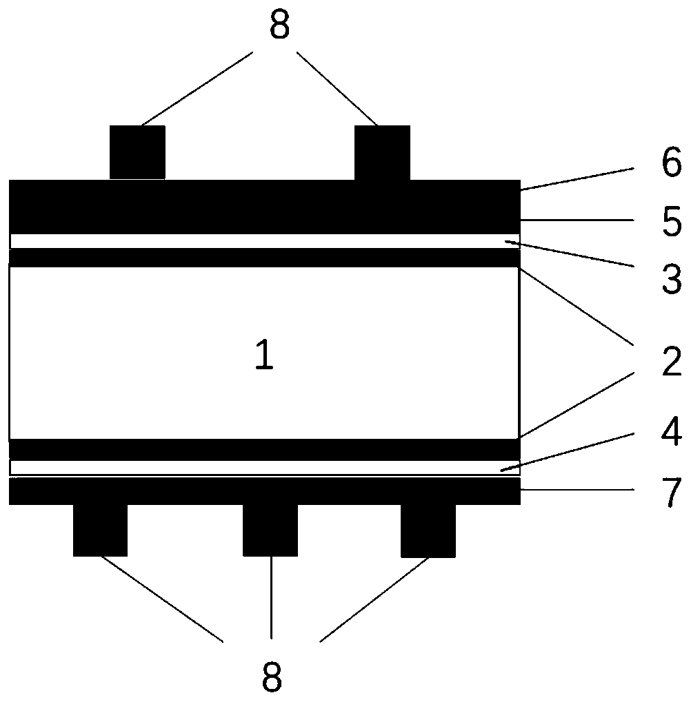
[0035] Such as figure 1As shown, a HJT battery includes an N-type silicon chip 1, the light-receiving surface and the backlight surface of the N-type silicon chip 1 are respectively provided with an intrinsic amorphous silicon layer 2, and the intrinsic amorphous silicon layer 2 on the light-receiving surface of the N-type silicon chip 1 A P-type doped amorphous silicon layer 3 is arranged on the silicon layer 2, an N-type doped amorphous silicon layer 4 is arranged on the intrinsic amorphous silicon layer 2 on the backlight surface of the N-type silicon wafer 1, and a P-type doped amorphous silicon layer 4 is arranged on the silicon layer 2. The silicon layer 3 is provided with an IMO layer 5 and an ITO layer 6 in sequence, an ITO conductive film layer 7 is provided on the N-type doped amorphous silicon layer 4, and a metal grid line electrode is provided on the ITO layer 6 and the ITO conductive film layer 7 respectively. 8.

[0036] In this embodiment, the work function of...


PUM

PropertyMeasurementUnit
electron work functionaaaaaaaaaa
thicknessaaaaaaaaaa
electrical resistivityaaaaaaaaaa

Abstract

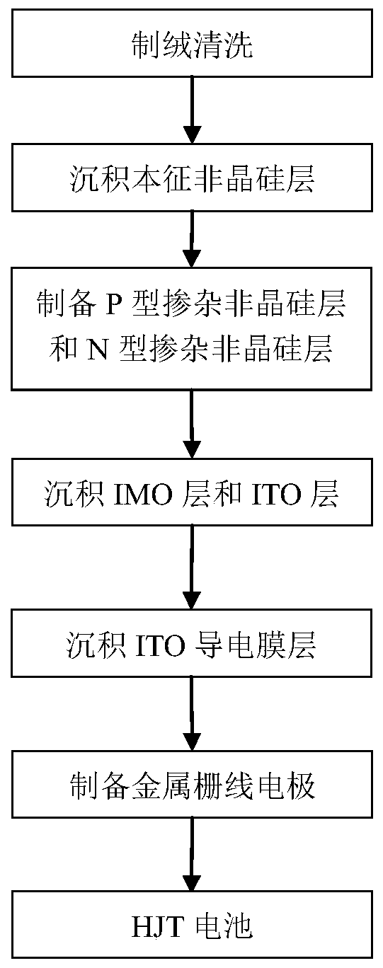
The invention discloses an HJT battery and a preparation method thereof. The battery comprises an N-type silicon wafer, wherein intrinsic noncrystalline silicon layers are arranged on the illuminatedface and shady face of the N-type silicon wafer respectively; a P-type doped noncrystalline silicon layer and an N-type doped noncrystalline silicon layer are arranged on the intrinsic noncrystallinesilicon layers respectively; an IMO layer and an ITO layer are arranged on the P-type doped noncrystalline silicon layer in sequence; an ITO conducting film layer is arranged on the N-type doped noncrystalline silicon layer; and metal gate electrodes are arranged on the ITO layer and the ITO conducting film layer respectively. The preparation method comprises the following steps: carrying out texturing cleaning on the N-type silicon wafer; and carrying out deposition / preparation of the intrinsic noncrystalline silicon layers, the P-type doped noncrystalline silicon layer, the N-type doped noncrystalline silicon layer, the IMO layer, the ITO layer, the ITO conducting film layer and the metal gate electrodes. The HJT battery has excellent electrochemical performance, and has extremely important meanings for improving the application range of heterojunction batteries, and the preparation method has the advantages of simple technology, low volume production threshold, low preparation cost,high production efficiency and the like.

Description

technical field [0001] The invention belongs to the field of solar cells, and relates to a HJT cell and a preparation method thereof. Background technique [0002] Solar photovoltaic power generation is a new power generation technology that uses the photovoltaic effect to directly convert solar radiation energy into electrical energy. It has the advantages of sufficient resources, cleanliness, safety, and long life. It is considered to be one of the most promising renewable energy technologies. It has become the fastest growing and most dynamic research field in renewable energy technology. [0003] Heterojunction solar cells (HJT cells) were first successfully developed by Japan's Sanyo Corporation in 1990. They are based on n-type monocrystalline silicon wafers and are sequentially deposited on the n-type c-Si front (light-receiving surface) that has been cleaned and textured. Intrinsic amorphous silicon film (i-a-Si:H) and p-type amorphous film (p-a-Si:H) with a thickne...

Claims


Application Information

Patent Timeline
Patent Type & Authority Applications(China)
IPC IPC(8): H01L31/0224H01L31/0747H01L31/20
CPCH01L31/022425H01L31/0747H01L31/202Y02E10/50Y02P70/50
Inventor 龙会跃成秋云周奇瑞罗志高李斌
Owner HUNAN RED SUN PHOTOELECTRICITY SCI & TECH
Learn More