Beam combiner packaging structure of high-power laser system

A laser system and packaging structure technology, applied in the direction of laser devices, laser cooling devices, lasers, etc., can solve the problems of poor long-term stability, poor heat dissipation effect of beam combiner packaging, etc., achieve easy operation, reasonable packaging structure design, and improve heat dissipation efficiency effect

Inactive Publication Date: 2019-11-05
DONGGUAN UNIV OF TECH
View PDF6 Cites 3 Cited by
  • Summary
  • Abstract
  • Description
  • Claims
  • Application Information

AI Technical Summary

Problems solved by technology

[0006] In view of the problems existing in the above-mentioned prior art, the object of the present invention is to provide a beam combiner packaging structure for a high-power laser system, by using a heat-conducting sealant material with high temperature resistance and high thermal conductivity and a thermal layer filled with a thermally conductive material, and selecting a high thermally conductive The metal is used as the packaging box to solve the problems of poor heat dissipation and poor long-term stability of the existing beam combiner packaging, so as to ensure the reliability of the beam combiner to the greatest extent.

Method used


Image

  • Beam combiner packaging structure of high-power laser system
  • Beam combiner packaging structure of high-power laser system
  • Beam combiner packaging structure of high-power laser system

Examples


Embodiment 1

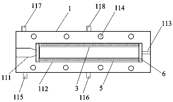
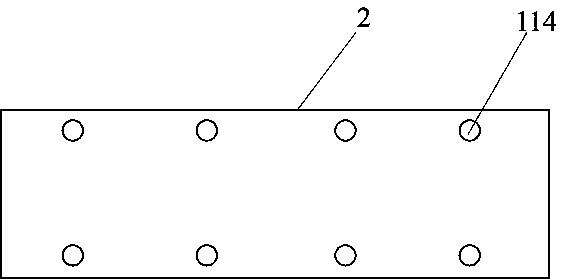
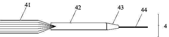
[0048] A beam combiner package structure of a high-power laser system, comprising a fiber beam combiner, a metal aluminum package base plate, a metal aluminum package cover plate and a quartz package sleeve, the base plate is provided with such Figure 4 The shown input fiber groove, rectangular groove and output fiber groove composed of several separated small grooves; the fiber combiner includes input fiber bundle, heat shrinkable tube, fiber bundle taper and output fiber; input fiber Each bare optical fiber of the bundle is put into the small groove of the input fiber groove respectively, and then penetrates into the heat-shrinkable tube together. The optical fiber is placed in the output optical fiber groove; the two ends of the packaging sleeve are respectively fixed with the metal box body with heat-conducting sealant, and the gap between the packaging sleeve and the rectangular groove is filled with heat-conducting materials; the side of the metal base plate contains two...

Embodiment 2

[0052] The package structure of a beam combiner for a high-power laser system provided in Example 2 is different from that in Example 2 in that the heat-conducting sealant is cured glue modified by hydroxyl-terminated polyborosiloxane, and the The heat-conducting material is a kind of insulating and heat-conducting silicone grease, which is composed of: 10wt% hydroxyl silicone oil, 0.6wt% silane coupling agent, 4wt% hydroxyl-terminated polyborosiloxane, and the rest is nitride ceramic powder; the silane coupling agent coated on the surface of nitride ceramic powder, and then mixed with hydroxyl silicone oil; the heat-shrinkable tube is prepared by the following steps:

[0053] a: Seal both ends of the quartz capillary with sealant;

[0054] b: After the glue is dry, wrap a layer of paraffin wax outside the sealant, so that the acid solution will not corrode the sealant and enter the inside of the capillary; tie a PTFE string that will not be corroded at one end of the capillar...

Embodiment 3

[0060] Compared with Embodiment 1, Embodiment 3 differs in that the metal box is made of red copper, and the others are the same as Embodiment 1.


PUM


Abstract

The invention discloses a beam combiner packaging structure of a high-power laser system, and the structure comprises an optical fiber beam combiner, a metal packaging bottom plate, a metal packagingcover plate and a packaging sleeve. An input optical fiber groove, a rectangular groove and an output optical fiber groove are formed in the bottom plate, and the input optical fiber groove comprisesa plurality of separated small grooves for respectively placing single input optical fibers; the side surface of the metal bottom plate comprises at least two groups of cooling water inlets and outlets; a gap between the packaging sleeve and the rectangular groove is filled with a heat conduction material. According to the invention, a high-temperature-resistant and high-thermal-conductivity heat-conducting sealant material and a thermal layer filling heat-conducting material are selected, and the high-thermal-conductivity metal is selected as the packaging box body, so that the heat dissipation efficiency of the packaging structure can be remarkably improved, the problem of poor long-term working stability of the high-power laser system beam combiner is solved, and the reliability and stability of the beam combiner are ensured to the greatest extent.

Description

technical field [0001] The invention relates to the field of fiber laser technology, in particular to a package structure of a beam combiner for a high-power laser system. Background technique [0002] High-power fiber laser systems have many advantages such as high conversion efficiency, high power, high reliability, long life, small size and low cost, and are currently widely used in industrial processing, biomedical, national defense and military fields. As the output power of the fiber laser system increases, the beam combining system becomes more and more complex, which poses a great challenge to the design and adjustment of the system, and also puts forward higher requirements for the skill level of the adjustment personnel. With the continuous increase of optical power, the current injected into the doped region is also continuously increased, resulting in the continuous increase of heat dissipation power in the doped region. If the heat generated during the operation...

Claims


Application Information

Patent Timeline
Patent Type & Authority Applications(China)
IPC IPC(8): H01S3/04H01S3/042H01S3/23
CPCH01S3/0405H01S3/0407H01S3/042H01S3/2383
Inventor 郭建文路崧曹锋王瑾孙振忠
Owner DONGGUAN UNIV OF TECH
Why Eureka
Try Eureka