
Submarine cable wiring design method for offshore wind power

A submarine cable and wiring design technology, applied in the direction of cable laying equipment, etc., can solve the problems of cable wiring increasing maintenance and repair costs of offshore wind farms, development restrictions, cost waste, etc., to reduce maintenance costs and repair costs, and reduce construction Cost, the effect of reducing wiring costs

Active Publication Date: 2019-11-05
SHANGHAI DIANJI UNIV
View PDF13 Cites 0 Cited by
  • Summary
  • Abstract
  • Description
  • Claims
  • Application Information

AI Technical Summary

Problems solved by technology

[0002] With the advantages of stable offshore wind speed, less impact on the surrounding environment, close distance from the load center and easy grid consumption, offshore wind power has gradually become the future trend of wind power development. With the further development of offshore wind power, the construction scale of offshore wind farms is gradually increasing. To expand, according to the statistics of the State Grid Energy Research Institute, the average investment cost of offshore wind power is about 2.8 times that of onshore wind power. Such a high cost of investment limits the development of offshore wind power. The proportion of the total investment is second only to the installation cost of wind turbines and the cost of construction engineering, which accounts for a large proportion. Due to the high cost of submarine cable wiring, the current scale of offshore wind farms is not large. At present, the submarine cable layout for offshore wind power , there are two wiring design methods in the industry: one is manual wiring based on experience, which is limited by the small scale of offshore wind power and uncomplicated wiring, which can barely meet the industry requirements, but there is a huge cost Waste problem; another kind of submarine cable route optimization considering the route abroad, using a single optimization algorithm to design the wiring of an existing small-scale single wind farm, but because the factors considered are too single, the optimization scenario is single, and it is only applicable to Path optimization in fixed scenarios cannot be properly routed according to user needs
[0003] Due to the constraints of construction safety requirements, submarine cable ampacity, power balance and other factors in China, manual wiring design methods based on experience are often used. The latest wiring design method only uses a single deterministic algorithm to optimize the cable length and model. , to find the lowest cost; foreign countries have proposed many intelligent optimization algorithms for optimization, such as genetic algorithm, harmony search algorithm, etc., but they still use a single algorithm for optimization
[0004] With the development of the scale of offshore wind farms, when faced with large-scale and complex offshore wind farms, due to the consideration of zoning and installation and maintenance, the existing technology can only reduce part of the cost of the initial construction, that is, the existing wiring design is only The length and type of cables are optimized, without considering other aspects of reducing the cost of offshore wind farms, such as transportation costs and landfill costs, later maintenance and overhaul costs, in fact, submarine cable routing needs to consider shore installation points to wind turbines In order to further reduce the cost, in the same way, due to the way the cable is laid on the seabed, and the existence of seabed surface gullies and submarine canyons, it shows that the straight-line distance on the sea surface is not equal to the actual distance, so the cost of filling the gully needs to be considered , in addition, unreasonable cable routing will inevitably increase the maintenance cost and overhaul cost of the offshore wind farm in actual operation

Method used


Image

  • Submarine cable wiring design method for offshore wind power
  • Submarine cable wiring design method for offshore wind power

Examples


Embodiment Construction

[0042] The present invention will be described in detail below in conjunction with the accompanying drawings and specific embodiments.

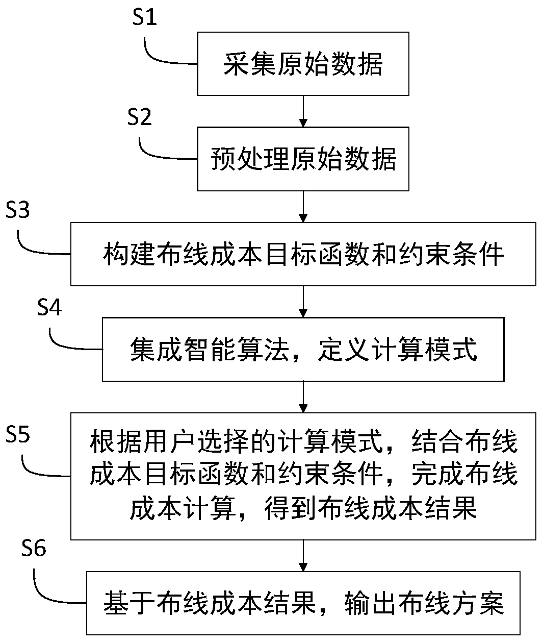
[0043] Such as figure 1 As shown, a submarine cable layout design method for offshore wind power includes the following steps:

[0044] S1. Collect raw data, where the raw data includes distance d, cable cost c, transportation cost t and landfill cost f, and distance d includes distance d between fans 1 , the distance between the fan and the transformer station d 2 , the distance between the transformer station and the load point d 3 ;

[0045] S2. Preprocessing raw data:

[0046] S21, removing the unique attribute of the original data;

[0047] S22. Perform interpolation processing on missing values ​​of the original data;

[0048] S23. Encoding the attributes corresponding to the original data;

[0049] S24. Standardize and regularize the original data;

[0050] S25. Selecting features corresponding to the original data;

[0051] S...


PUM


Abstract

The invention relates to a submarine cable wiring design method for offshore wind power. The method comprises the following steps: S1, collecting original data; S2, preprocessing the original data; S3, constructing a wiring cost objective function and constraint conditions; S4, integrating an intelligent algorithm, and defining a calculation mode; S5, according to the calculation mode selected bythe user, in combination with the wiring cost objective function and the constraint condition, finishing wiring cost calculation to obtain a wiring cost result; S6, outputting a wiring scheme based onthe wiring cost result. Compared with the prior art, the method has the advantages that the wiring cost objective function is established, and the wiring distance, the cable cost, the transportationcost and the landfill cost are multiplied by the influence factors to serve as the objective function; and meanwhile, non-overvoltage and non-overcurrent of the submarine cable are used as constraintconditions, and an integrated intelligent algorithm is used for solving, so that the wiring scheme with the lowest wiring cost is obtained, and the reasonable cable wiring design can be generated according to user requirements when a large-scale offshore wind farm is constructed.

Description

technical field [0001] The invention relates to the technical field of offshore wind power, in particular to a submarine cable layout design method for offshore wind power. Background technique [0002] With the advantages of stable offshore wind speed, less impact on the surrounding environment, close distance from the load center and easy grid consumption, offshore wind power has gradually become the future trend of wind power development. With the further development of offshore wind power, the construction scale of offshore wind farms is gradually increasing. To expand, according to the statistics of the State Grid Energy Research Institute, the average investment cost of offshore wind power is about 2.8 times that of onshore wind power. Such a high cost of investment limits the development of offshore wind power. The proportion of the total investment is second only to the installation cost of wind turbines and the cost of construction engineering, which accounts for a ...

Claims


Application Information

Patent Timeline
IPC IPC(8): H02G1/10
CPCH02G1/10
Inventor 刘扬刘三明牛壮壮
Owner SHANGHAI DIANJI UNIV
Features
  • Generate Ideas
  • Intellectual Property
  • Life Sciences
  • Materials
  • Tech Scout
  • Unparalleled Data Quality
  • Higher Quality Content
  • 60% Fewer Hallucinations
Learn More