

Continuous operation steam explosion unit
A steam explosion machine and steam explosion technology, applied in feed, grain processing, food science, etc., can solve the problems of limited volume of steam explosion chamber and low operation efficiency, and achieve high work efficiency, continuous operation, and convenient and fast steam explosion operation Effect
- Summary
- Abstract
- Description
- Claims
- Application Information
AI Technical Summary
Problems solved by technology
Method used
Image

Examples
Embodiment Construction
[0021] The present invention is described further according to accompanying drawing:
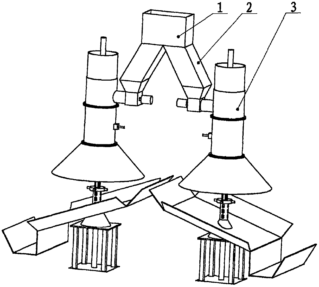
[0022] A continuous operation steam explosion unit is mainly composed of a feed distributor 1, a material delivery pipeline 2 and two or more continuous operation steam explosion machine units 3, and the feed distributor 1 is connected to the continuous operation steam explosion machine through the material delivery pipeline 2 Unit 3 is connected.
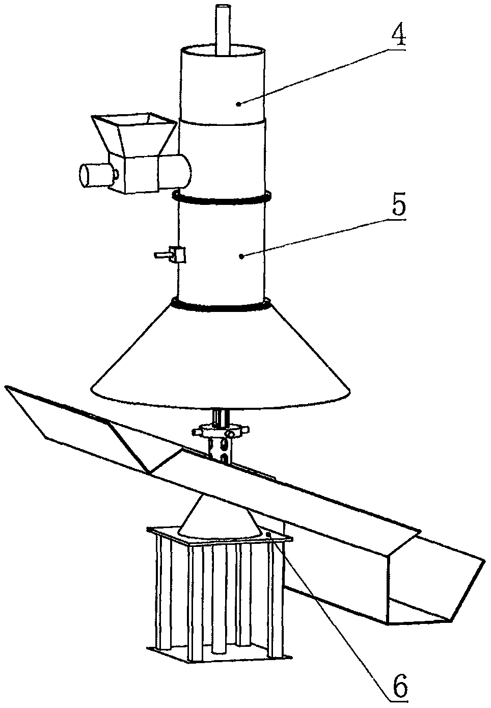
[0023] Continuous operation steam explosion machine unit 3 is mainly composed of feed compression piston 4, feed steam explosion cylinder 5 and support frame 6, wherein feed compression piston 4 is mainly composed of compression piston barrel 23 and feed compression piston oil cylinder 22 , are connected by flanges.
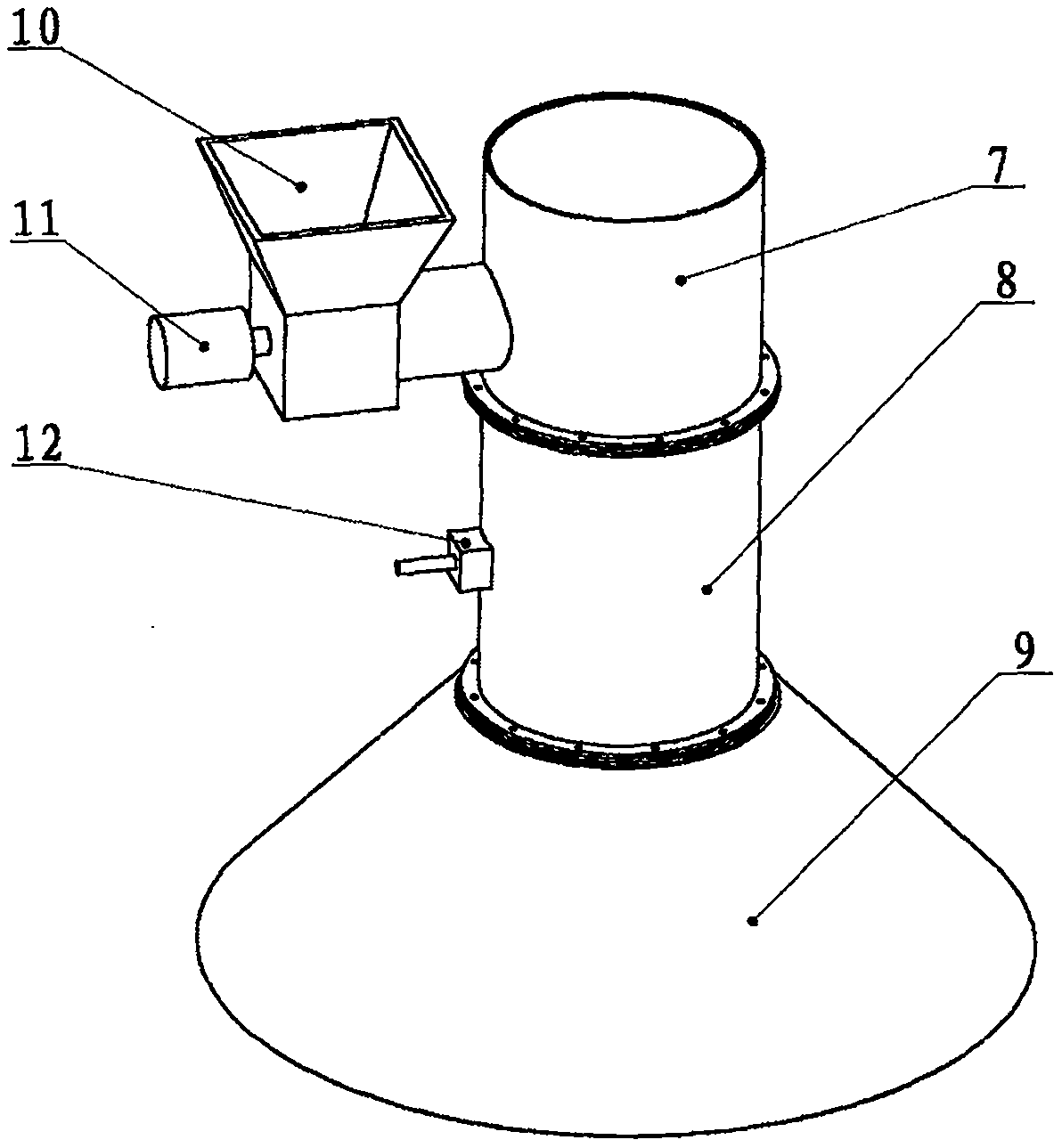
[0024] The feed steam explosion cylinder 5 is mainly composed of a feed cylinder 7, a steam explosion cylinder 8, a material guide muffler cover 9, a steam inlet flange 12, a hopper 10, a forced conveying screw 24 and a motor 11. T...
PUM
 Abstract
Description
Claims
Application Information