Large rotating inertia light composite flywheel for satellite and preparation method thereof

A large rotation and flywheel technology, which is applied to aircraft, motor vehicles, aerospace equipment, etc., can solve problems such as mismatching, satellite flywheels to reduce the demand for large moment of inertia, etc., to ensure continuity and uniformity, and to meet the balance of large moment of inertia The effect of stabilization requirements

Active Publication Date: 2019-11-08
AEROSPACE RES INST OF MATERIAL & PROCESSING TECH +1
View PDF9 Cites 5 Cited by
  • Summary
  • Abstract
  • Description
  • Claims
  • Application Information

AI Technical Summary

Problems solved by technology

[0004] The technical problem solved by the present invention is: to overcome the above-mentioned defects of the prior art, to provide a large moment of inertia lightweight compo

Method used


Image

  • Large rotating inertia light composite flywheel for satellite and preparation method thereof
  • Large rotating inertia light composite flywheel for satellite and preparation method thereof
  • Large rotating inertia light composite flywheel for satellite and preparation method thereof

Examples


preparation example Construction

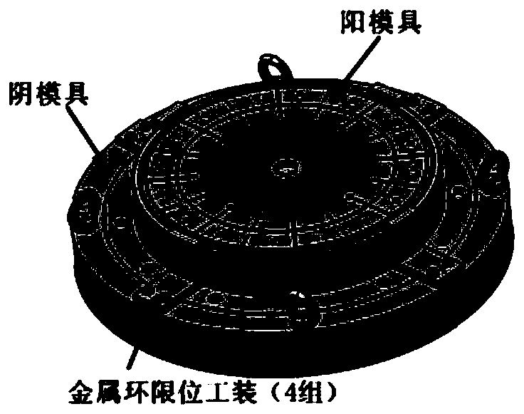
[0036] The preparation method of the satellite with a large moment of inertia lightweight composite flywheel comprises the following steps:

[0037] 1) The design molding mold is a combination mold composed of female mold + male mold + metal ring limit tooling. The male mold is composed of steel split male module + silicone rubber soft module, and the female mold is composed of integral concave mold + silicone rubber soft module. Modules are combined, as shown in Figure 3;

[0038] Specifically, in the embodiment of the present invention, the mold is designed with a suitable combined mold according to the structural characteristics of the flywheel. The material of the mold is preferably Q235 steel, 45# steel, and P20 steel. Silicone Rubber.

[0039] 2) Lay layers on the surface of the male mold and the female mold respectively: the prepreg on the surface of the female mold extends outward along the horizontal plane to the inner position of the corresponding metal ring on the ...

Embodiment 1

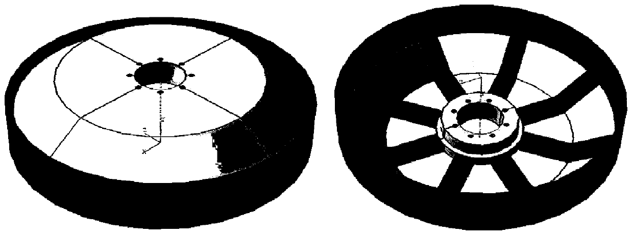
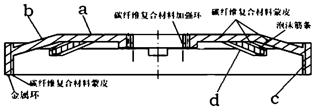
[0054] see Figure 1-2 , the large moment of inertia lightweight composite flywheel for the satellite described in the embodiment of the present invention, the flywheel includes a metal ring, a carbon fiber composite material skin, a carbon fiber composite reinforcement ring and foam ribs; the carbon fiber composite reinforcement ring is in the shape of a ring, The metal ring is located on the outermost side of the entire flywheel, the carbon fiber composite skin is located between the reinforcement ring and the metal ring, and the foam ribs radiate outward along the outer edge of the reinforcement ring and are evenly distributed between the reinforcement ring and the metal ring used to increase the stiffness of the flywheel.

[0055] The carbon fiber composite skin includes a plane, a circular surface, a cylindrical surface and a convex surface; the plane is coplanar with an end face of the carbon fiber composite reinforcement ring, and the circular surface is non-coplanar wi...

Embodiment 2

[0071] The large moment of inertia lightweight composite flywheel for satellites described in the embodiment of the present invention includes a metal ring, a carbon fiber composite skin, a carbon fiber composite reinforcement ring and foam ribs; the carbon fiber composite reinforcement ring is in the shape of a ring, and the metal The ring is located on the outermost side of the entire flywheel, the carbon fiber composite skin is located between the reinforcement ring and the metal ring, and the foam ribs radiate outward along the outer edge of the reinforcement ring and are evenly distributed between the reinforcement ring and the metal ring used to increase the stiffness of the flywheel.

[0072] The carbon fiber composite skin includes a plane, a circular surface, a cylindrical surface and a convex surface; the plane is coplanar with an end face of the carbon fiber composite reinforcement ring, and the circular surface is non-coplanar with the plane Surface, the cylindrica...


PUM

PropertyMeasurementUnit
Concentricityaaaaaaaaaa
Elastic modulusaaaaaaaaaa
Densityaaaaaaaaaa

Abstract

The invention provides a large rotating inertia light composite flywheel for a satellite and a preparation method thereof and relates to the technical field of composite materials. The large rotatinginertia light composite flywheel for the satellite is applied to a metal and composite material co-curing and integrally-molded composite material member and is a key technology for realizing preparation of a light large rotating inertia flywheel for the satellite. The large rotating inertia light composite flywheel for the satellite comprises metal rings, carbon fiber composite material skins, carbon fiber composite material reinforcing rings and foam ribs. A forming mold consists of combined female mold and male mold and metal ring limiting tools; a male mold consists of a steel segmented male mold block and a silicon rubber soft mold; a female mold consists of an integral concave mold and a silicon rubber soft mold block. The skins, the reinforcing rings and the ribs of the large rotating inertia light composite flywheel for the satellite adopt continuous fiber prepreg to realize the making of a prefabricated part, and then the metal rings sleeve the external side of the prefabricated part, and the co-curing and molding of the large rotating inertia light composite flywheel for the satellite are realized by using a hot pressing process. The developed large rotating inertia lightcomposite flywheel for the satellite satisfies requirements on the rigidity and the strength of reducing the weight and centrifugal force of a wheel body and also satisfies large rotating inertia equilibrium stability requirements.

Description

technical field [0001] The invention belongs to the technical field of advanced composite materials, and relates to a large moment of inertia lightweight composite flywheel for satellites and a preparation method thereof. Background technique [0002] The momentum flywheel uses momentum exchange to achieve satellite attitude control and state stability. Compared with chemical battery energy storage systems, it can make satellite energy storage systems have the advantages of higher specific energy, high efficiency, high reliability, and wide operating temperature range. It can be used in a long-life, high-reliability satellite control system platform. At present, domestically produced satellite wheels are all one-piece structures, mostly made of high-strength steel. Due to the large weight of the wheels, they have high requirements for rotating bearings, and it is difficult to meet the use requirements of lightweight satellite platforms and high moment of inertia flywheels in...

Claims


Application Information

Patent Timeline
IPC IPC(8): B64G1/28B29C70/34B29C70/68
CPCB29C70/342B29C70/68B64G1/285
Inventor 杨智勇孙宝岗杨昆晓孙荣庆史汉桥郭鸿俊程雷张艺萌
Owner AEROSPACE RES INST OF MATERIAL & PROCESSING TECH
Why Eureka
Try Eureka